Electronics notes/Knobs and dials
Potmeters
Variable resistors (see potmeters), many of the ones with a knob are single-turn, meaning they go though their resistance range in usually at most 300 degrees of rotation.
This makes them useful as absolute-position rotation sensors.
Not overly accurate ones, but cheap and fairly durable.
Rotary/linear encoders
Incremental encoders, a.k.a. Relative encoders (only) report/detect change in position, from which you can calculate direction and speed. ...assuming you're sampling fast enough to not miss transitions.
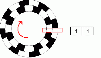
The idea behind incremental encoders is roughly that they're seeing two things 90 degrees out of phase
One way is to use a a quadrature encoding disc.
You read these out with two sensors at the same angle (e.g. the red bar in the image on the right is two sensors).
You can detect speed based on how the rate of state changes, and detect direction based on the sequence (which one leads the other).
There is a variant of that idea in how many mouse scrollwheels (and opto-mechanical ball mice before that) work: a wheel with a single set of slits, and sensors offset less than(verify) half the slit distance, which effectively has a response very similar to a quadrature disc.
This is effectively the same in terms of what you do with the output.
As-is, relative encoders are useful for things like menu navigation, where only movement matters in the first place, and when sensing speeds.

Absolute encoders report their actual position, from which you can then infer direction and speed.
You could intuit these as encoding their position as an integer, but they're actually Gray code, more useful in this context because it lets you detect and potentially correct successive values that don't make sense after the last.
Virtual absolute encoder (TODO)
Readout
In terms of electronics or code
Resolver
https://en.wikipedia.org/wiki/Resolver_(electrical)
Considerations when using switches as input
On floating inputs
Consider that switches often either connect or disconnect an input, meaning one state is a broken circuit.
This means there is nothing to pull it to a stable state,
and EM from nearby ICs or the environment can be the strongest effect, particularly if the traces are longer.
What we have made is antenna. Not a very efficient one, but if we sense it with high impedance inputs,
we are still measuring the basic EM around us.
If we thought we were just hooking up a switch, we would call that "pretty damn unpredictable behaviour".
Solutions are somewhat context dependent.
The easiest fix is often a pullup/pulldown resistor.
- A lot of microcontroller platforms, DIY or not, you can enable an internal pullups via code, which means you don't need to add a physical resistor to such a circuit.
Pullups/pulldowns tend to be fairly stable in that it now more induced current to change the input,
more than the usually-tiny amount of EM around us is capable of.
...unless that's not true, e.g. and/or it's smushed right up against a moderate source, or you have a stronger EM. Say, industrial setups and nightclubs are less friendly than your desk (mostly. LED lighting is often moderately dirty).
Note that these internal pullups tend to be high-valued (e.g. order of 50K), and when
- traces are long, and/or
- you have no shielding, and/or
- you work with high-EM environments (industry, nightclub), and/or
- you are working with SoCs that assume they live in shielded cases and short traces (e.g. RPi's SoC), and in reality they do not
...then that pulldown may not be enough to pull down enough to quiet down EM noise enough, and you can still get noisy input, spurious interrupts, and want to add your own resistors, and maybe values maybe on the order of 5-10k (lower resistance is surer, but interferes with higher speed IO).
Buffers and various logic ICs may have unused elements, which might actually be switching wildly due to their inputs floating, and their output might induce a little noise nearby, even if not connected. You can avoid that, for nearly-free, by tying their inputs to Vcc or Gnd.
Bouncing
The mechanics in almost all switches means when you change them to their other state, their contacts will physically bounce, and this short-term variation in mechanical contact is mirrored in the electrical contact, so it amounts to very fast electrical switching (in particular when read out by something with high input impedance).
Contacts where you stay in direct contact with the contact area, e.g. the cheapest doorbells, will continue to make intermittent contact as you move your fingers (on contrast with clickier switches, which often implies throwing a spring loaded thing around).
We may also call that bounce, in part because we can often resolve potential issues in a similar way. (and once you include this, also keep in mind that corrosion from moisture, dirt, smoke, and such will change the exact contact behaviour over time)
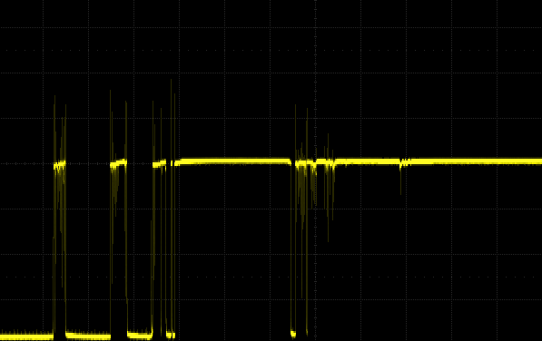
Bounce timespan
The mechanics of small latching switches tend to settle within 10 or 20ms.
Most of the mess may happen within the first few one or two milliseconds - but that varies per switch type, and size.
You may like to see what that looks like when sampled, like the image on the right, though the details vary a little with mechanics and size of each button.
Keep in mind that capacitive effects will change the shape of that - traces like this are often lab-conditions with reasonable pullups/pulldowns, and high input impedance (because oscilloscope)
Bounce on disconnect versus bounce on making contacts
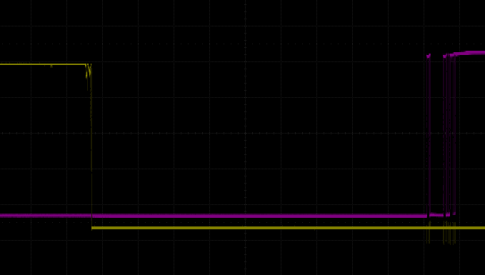
I had both cleaner and dirtier variants of that yellow-leaving part (and this is a fresh switch, it might be a little worse if corroded/arced with use).
The vertical offset between the traces is just there to not overlap them
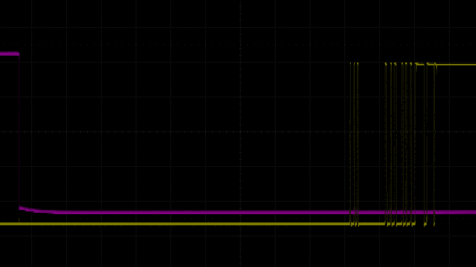
In various switch designs, breaking a contact tends to be cleaner than making the same contact.
Intuitively, consider momentum-like reasons: if a contact gets flung by a spring-like thing, there's more energy to waste at the end of a movement/acceleration, and very little at the start. It may still have a scratchy start, though, so it's not perfect.
The oscilloscope traces on the right are from
a non-latching pushbutton (which is still fairly clicky, and stable on both sides),
that has both normally-open and normally-closed contacts (alternatively, seen as SPDT).
The first image is from when it is pushed in, the second when it is released. You can see that in both cases, the action of leaving is cleaner.
Don't think that this is a full solution, though.
For one, the actual physical contact of a switch still depends with the physical layout of that switch. This happens to be a fairly clean case, others are not.
Also these two images are cherry-picked. Even this fresh, never-saw-an-arc button also had dirtier traces (though still not nearly as messy as arriving contacts).
So sure, debouncing a contact break may be simper and faster - but if you think you have to do little or no debouncing,
then you or your clients will be rather unhappy some time later.
(...and yes, there is delay between the two (roughly ~1.5ms), which is mostly just physical travel between the contacts. Think of it as a SPDT switch)
Not all switches's bounce is created equal
See also the debouncing-method plot below - already shows some different delays and contact patterns from different buttons under test
The mechanics of specific switch/button design ends up mattering.
Some types of switches bounce more than others.
For example, a classical doorbell maybe bounces less, but may also have imperfect contact while you hold it (looks like fast switching), which you would also call bounce. It may be faster than some alternative, but also less predictable - and this will change over time as the contacts corrode.
For the same design, smaller switches may bounce less.
On the other hand, something with a click, like a microswitch, will probably bounce a little longer but is effectively more stable in each state even though it is functionally as momentary as the doorbell-style pushbutton.
Practical problems
Turns out something as simple as buttons can be an engineering design question, for mostly stupidly practical reasons.
Images like the above look clean for lab-condition and cherry-picking reasons, but in the real world
- there are different kinds of buttons,
- there are different sizes of buttons,
- there are capacitive effects,
- there are sampling impedance details,
- the contacts will oxidize over time,
- the contacts will pit if arcs happen (when they control power),
- there are details to how e.g. logic-level interpretation sees this signal
Point being made: you rarely control all the details, quantifying this is hard, So even if you fix it very precisely for this switch, wire, and circuit today, exactly the same may fail to work in another device, or in the same device a year from now.
You can easily see dozens of bounces in a millisecond - which is moderately high frequency switching - can be kHz range.
Problems for control signals / Not all inputs are created equal
- logic circuits might act on every single edge - so may react thousands of times for what you want to think of as a single human/mechanical input
- same for microcontroller inputs configured for interrupts
- some components will get very confused if they see very quickly switching signals on their inputs
- bounces can be short enough to be considered kHz range
- microcontrollers that just occasionally sample the input miss most of that
- sampling moderately fast is actually a cheap way to debounce
- though sampling too slowly may miss the press entirely
- also note sampling slowly means slower response to the press
- Microcontroller pins tend to have impedance somewhere between 100k and 1MΩ (verify)
- the pullup/pulldown impedance may be specced differently. E.g. AVRs seem to be between 20k and 50k, RPi between 50k and 60k (which can be more sensitive to EMI).
Different combinations of these, and what you connect, work out as different amount of sensitivity to EM. (one reason that pullups you add yourself are usually 10k or maybe even a little smaller)
Problems when switching circuits directly
- Simpler loads often don't care so much, so this is often fine
- larger inductive loads will resist current change - so lead to arcing in the switch, which makes the contact rougher, and the switch output change over time
- you may not like switching inductive loads so fast (due to flyback it produces for you)
- Some electrical components that don't like switching that fast
- e.g. say switching power to a microcontroller is valid enough in theory, but it may really dislike bounce on its Vcc (it might actually confuse its boot - what not to do on Vcc should be documented, though)
- for a mains power switch, switching main power that fast might (due to LC-like circuits) send a mess of spikes that only settles once the switch does
Not all environments are created equal
Could you react to the first change in under 1ms? Sure.
Will that work on you desk in your lab? Absolutely.
Will that work shoved into, say, a nightclub (lots of devices leaking EM everywhere)? If you're lucky. If not, it may react to each blink of the lights.
Will that comply with certification? Probably not.
Could you get away with it in DIY? Probably.
Would it practically hold up as a solid product? Probably not.
Debouncing
Software debouncing
- ...are mostly variations on the idea that when pressed, a button would be in actuated state most of some recent time before we consider it pressed
- e.g. the most basic arduino debounce code essentially just samples twice, typically 25ms or 50ms apart
- and effectively says "if the last two samples are high, ourput is high". This feels a little cheaty but consider:
- two random samples in mostly-non-actuated are unlikely to both be high (unless there is a lot of EMI around)
- two samples during a actually-pressed bouncy transition are still only moderately like to agree
- if pressed, you often get either one sample within transition and one settled, or two settled, and both work decently (with some difference in delay)
- upsides
- the likeliness that both sample high when the button is pressed is nonzero, but usually are or can be made be made very low (and there are ways to lessen the EM noise issue)
- so works quite well for something so simple and CPU-cheap to implement (does not need to wait, sampling a GPIO takes order of microseconds(verify))
- the larger the time, the more that you limit fast oscillation (because you only change your decision slowly), and the less likely it is to oscillate overall (most switches will be stable after a while)
- limitations:
- fragile around significant EM noise (mostly because high impedence sensing is sensitive
- regularly a somewhat lower-valued pullup/pulldown is a good workaround, though this takes some consideration of the circuit
- the more stable you want it, the slower it needs to be, and the converse:
- becomes somewhat more fragile if you lower the interval too far (limitation determined by the mechanics of the switch)
- we don't know about the first edge, we just sample at a random time - so it's not the fastest or most consistent method anyway
- fragile around significant EM noise (mostly because high impedence sensing is sensitive
- and effectively says "if the last two samples are high, ourput is high". This feels a little cheaty but consider:
- sample more frequently, count up when pressed, count down when not, and use a threshold
- on average can react a little faster than the previous method (in part just because you are very likely to sample one or two orders faster)
- has is a tradeoff between speed and robustness - but this is more gradual (how fast to sample, how high to count) and tweakable (e.g. counting up faster than down biases it a little faster).
- can still oscillate if the whole manages to float around that threshold. This is fixable with some intentional hysteresis
- rolling average (e.g. EWMA), much like the RC circuit below
- more computationally expensive, though, and particularly with a small alpha will just be a slower implementation that is functionally the same as the the counting method
- most methods are best tuned somewhat for the speed of switching and sampling.
In analog circuits / components
- filter and threshold
- e.g. RC circuit filter [1]
- the RC filter can be thought of as a slowish charger towards while being pressed. If there is a lot of bouncing but it's still mostly connected, this merely slows that charging a little. Transients contribute to charge but are not a toggle themselves.
- may still oscillate, because there is no hysteresis or latching. This is why you might go for a Schmitt trigger
- you want to choose the RC values for the worst possible case of bounce time, plus a margin of pessimism and to include things you didn't think of like humidity (maybe three times the typical bounce time)
- it also delays the time at which the signal is high enough (but this is true in most debouncing)
- if it's SPDT toggle (so we have one contact, a considerable space of hi-Z, and another contact) or
- then you can use a flip-flop circuit to have it latch (can be faster, though you might still want some filtering to be insensitive to EMI)
- there are some similar solutions with specific logic chips, inverters, transistors,
Notes:
- debouncing will almost necessarily slow down the decision, compared to 'react to absolutely every edge/high at the highest speed you can manage'
- ...but for human-operated switches, a dozen-millisecond reaction is more than enough (also the mechanical limit at which you can even press most switches - even most gamer keyboard don't try for much more than this)
- different methods may have different inherent latency
- the ability to bias it also varies per method
- there are exceptions, like the DT toggles
- the above mentions the possibility of oscillation.
- with the nature of most switches, oscillation won't happen very often, but still something to think about in serious designs
- if your load doesn't like fast switching (or if the thing you send a control signal to will get confused by it),
- then consider holding off a next action until some time after the most recent action taken (sometimes easier to do in code than in components)
- if the thing you control has safety implications, then you may want to bias your debouncing to whatever state is safer
- (or, similarly, less annoying, or otherwise preferable)
- there are some implementations that you can bias to one way (e.g. a pushbutton is considered non-pressed until it's fairly consistently on) - but beware of variants of that code that will effectively debounce in one direction but not in the other, because that may have different implications
- With double throw switches, you effectively have three states (connected one way, connected the other, inbetween/unsure), and you could latch to one side until you see the other (and have the inbetween have no effect).
- Relatedly, environments that produce a lot of EM noise may also produce a mess on your high-impedance inputs.
- While being more immune to EM noise usually has better solutions (shielding, lower-value pullups/pulldowns), debouncing tends to also reduce the amount of false triggers due to EM (wheth).
TODO: write up a fuller explanation, including common avoidable mistakes
Example of software-debounced results
A few different switches and buttons, sampled fairly quickly, and debounced.
The following also tries to illustrate that different kinds and sizes of switches may have different bouncing behaviour (though fails to show the effect of things like corrosion - the pushbuttons seem good now but are more likely to become worse over time):
Notes:
- colors:
- Blue lines and blue fill indicate the raw button state, which is boolean, because it's read with digitalRead (itself effectively a thresholded version of varied voltages).
- The yellow fill is debounced via the simple interval method, "it's high now and it was high X amount of milliseconds ago" (evaluated with that same amount of millisecond interval, which is part of why this is also fairly stable output-wise - but also comes at a random time after initial event at least in this implementation)
- The purple line is the counter method, showing the increasing counter with a line, and a purple fill once it's above the (somewhat low) threshold.
- Both methods would absolutely still flip-flop fairly quickly (or, on the other hand, act relatively slowly) if tuned wrong.
- In this example they are both a the tightest value they won't flip-flop at. This is cheating given this particular data - in general you usually want to trade away speed, for more more robustness (and methods may become of more comparable speed when you do that anyway).
Switches, buttons, toggles, and such
Encompasses combinations of:
- Multiple positions,
- a mechanical tendency to go to one position
- toggle/flip, or momentary
- multiple electronic states,
- and other electronic properties
Bistability refers to switches that will rest in both states.
It could be both a mechanical and electronic descriptor, though on the mechanical side it's often called latching, or some such term, whereas a monostable would refer to what most relays do (the term "monostable switch" would be rare because we have words like "momentary" and "pushbutton").
...so the terms monostable and bistability are usually about electronic switching, e.g. to pointing out e.g. that
- digital circuits can be made to sustain their current state.
- thyristors will stay in their current state, while transistors are not
- ...often then mentioning a simple bistable multivibrator circuit, a.k.a. flipflop), or contrasted with a monostable multivibrator
See also
Types
pushbutton tends to refer to any momentary thing, a switch frequently to something that stays in whatever state..
When shopping, it helps to know some names more specific than "small switch". A few more specific buttons/switches:

Toggle switch
- states: often two, sometimes three. Often toggled, rarely momentary
- toggle switch
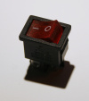
Rocker switch
- states: often two, sometimes three. Often toggled, sometimes momentary
- rocker switch

Microswitch
- mainly a small momentary push-button
- states: Two. Momentary.
- with or without a metal leaf as a lever
- microswitch
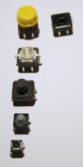
Tactile switches, probably referring to their clicky nature
- momentary

DIP switches
- usually internal, for changeable device configuration that can't be acidentally changed
Reed switch
- states: Two.
- Mechanical, closed by nearby magnet
- reed switch
Mercury switch
- states: Two. Depends on orientation (because gravity).
- no contact bounce
- mercury switch
Knife switch
- The circuit breaker of old
- states: Two. toggled
- knife+switch
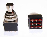
Footpedal switches (mostly seen around guitar pedals)
- the 9-pin are typically three separate latching switches (3PDT)
- these also exist in other variants, like single SPDT, momentary (SPST, for taps), and a few others
Uses:
- end switch
- a switch positioned at the end of a mechanical range, often to detect when actuation should go no further
- often a microswitch with some sort of lever, wheel, etc. for durability.\
- end+switch
Contact bounce (behaviour)
Contact bounce indicates the time in which an arriving contact mechanically settles and in which the connection is not yet stable. See some images. This bounce is often tiny, both in movement and time.
This bounce is rarely important when driving resistive loads, but in anything more complex there the reaction to the bounce itself can matter.
For example, a digital system observing/sampling it may see very fast switching back and forth.
Some components, such as ICs, also don't deal too well with bounce on their Vcc. A bypass capacitor helps here, and is nice for its power stability anyway.
Arcs (behaviour)
Default switch state (design)
Switches that are typically in one state are often can be referred to as Normally Open (NO) and Normally Closed (NC), roughly meaning they will return there unless actuated otherwise.
If it has contacts for more than one state (which, when one state is most natural, can be termed NO and NC contacts), the switch is termed Changeover (CO) (also Double-Throw, implying a typical two-state switch, Triple-Throw, etc.).
Changeover switches can be:
- break before make, meaning there is some time in which neither side makes contact. This may cause temporary high impedance long enough to cause some unpredictable behaviour
- make before break, meaning there is some time in which both sides make contact. This may easily cause temporary shorts.
Poles and throwing (design)
Depending on what exactly you want to do, poles and throws can matter when buying a switch.
Amount of poles matters to whether you want to do something with one state (e.g. powered or not) or with both.
Amount of throws matters when you want to control things independently from the same mechanical switch (without digital logic doing it for you). Consider that a car's emergency light switch turns on both turn signals without tying them together electrically.
In some constructions, both matter. Consider multiway switching.

- SPST (Single Pole, Single Throw)
- open or closed

- SPDT (Single Pole, Double Throw)
- a common lead switched between two other leads.
- Used e.g. in multiway switching

- DPST (Double Pole, Single Throw)
- two separate SPST-style switches controlled by the same mechanics

- DPDT (Double Pole, Double Throw)
- two separate SPDT-style switches controlled by the same mechanics
There are further variants of design, variations on the same themes.
Triple pole and similar also exist, for example
- three-phase mains knife switches are essentially 3PST (some are 3PDT)
- 9-pin guitar pedal switches are typically 3PDT
Relays
A relay is an electronically controlled switch - a switch you can flip remotely.
Relays switching an electronically separated circuit can be useful when they deal with different voltages and/or different orders of current.
Say, microcontrollers switching mains equipment.
Relays are also make sense around more modular systems, like process control,
because it's easier to separate control signals from drive currents,
e.g. via connectors following some convention.
Also to have them be plug-and-play replacable.
Electromechanical relays are the classical variant, specifically a solenoid that pushes/pulls a contact closed.
Being the main and only type for a while they are often called just relays - or EMR in contexts where SSRs are also relevant (like here).
Solid state relays (SSR) are a relatively new development, and are becoming more common.
SSRs seem to often be either
- for switching AC or DC loads: a SCR or TRIAC with the appropiate control circuitry to make them work basically like relays (and may be isolated too)
- for switching only DC loads: a MOSFET
...plus heatsinking, optical coupling for isolation, and some other considerations.
There are also Reed relays, which can switch faster than EMRs, but have a current limit that is often on the order of half an amp tops. They are mostly associated with some oldschool analog electronics.
In general, your choice is between EMR and SSR. There is more comparison below, but in general, EMRs ar chunkier but wear over time, while SSRs take a bunch more design care but can then be more flexible.
Circuit considerations - control side
EMRs may need need on the order of 20mA-50mA to be held consistently. More when switched from lower voltages, less from higher voltages.
Because EMRs are coils, they are inductive elements that present flyback to the circuit that drives them, so you may want to sink that flyback spike elsewhere, particularly if controlled from ICs.
Circuits with ICs driving them
- typically something (probably a diode) for flyback protection of that transistor/optocoupler.
- regularly use a transistor (sometimes an optocoupler) to drive ~50mA even when the control
SSRs use less control current(verify), but run hotter overall due to their semiconductor nature, so
- you may need a heatsink or risk thermal runaway (read: smoky melty problems), particularly in already-warm conditions
- for safety's sake assume approx 1W of heat per 1A drawn, though usually it's noticably less
Circuit considerations - load side
Relay ratings
Not all relays are created equal.
The physical design will vary with the voltages they are intended to switch.
- Most are designed for at most mains voltage, because arcing is harder to design away at kilovolts.
- Relays designed for at most dozens of volts can switch faster because they barely have to think about arcing as an .
Relatedly, when switching significantly capacitive/inductive effects, you will briefly see larger currents and voltages (the inrush current of the load).
- This is one reason a relay's maximum rated inductive load is much lower, often well under half the rated maximum resistive load.
- For example, the one I'm holding right now is rated for 10A (at 125VAC and 240VAC) for resistive loads, and for 3A for inductive loads.
- This too depends somewhat on the voltage.
- Specifying these differences is called 'derating
There is also a difference between whether it's switching AC or DC.
- Because DC can sustain an arc longer, DC is derated more(verify).
- Check the datasheet, the ratings printed on the relay may be correct but less complete.
Hot switching refers to switching a relay while voltage is applied, which matters mostly to mechanical relays in that it produces arcing and wear.
Cold switching refers to applying voltage only after a relay switch.
Cold switching is possible to design into some test equipment, and sometimes useful to concentrate the wear in a predictable place, but in general many uses of relays will be hot switching.
Note that while it may seem that using a relay for much less current than it is designed for should avoid all wear issues (no arcing), it seems this actually can make them get dirty instead (?oxidation?(verify)), meaning they will fail to work reliably.
Comparison between SSRs and EMRs
- switching speed
- SSRs can switch at perhaps 20usec..10msec. That said, ones that have zero cross switching are by definition slower.
- EMRs at order of 50ms and wear faster in the process
- SSRs can switch much larger currents without much higher drive currents
- SSRs that do zero point switching means no sudden current change
- so they don't pollute the waveform as much(verify)
- EMRs have contact bounce
- and, when hot-switching, arcing, welding, and shortened contact lifespan
- this is worse on inductive loads
- EMRs are more susceptible to shock, and orientation matters
- SSRs are preferable around strong vibration (to avoid intermittent contacts, amplifying bounce)
- SSRs are preferable when they have to be close to magnetic sensors, temperature sensors
- SSRs can be preferable in humid and dusty environments (but you may want to protect the entire PCB with an enclosure, so this often matters less)
- current draw
- larger EMRs have to push larger contacts
- SSRs are higher resistance by nature, so use a few times more hold current
Safety-wise
- EMRs arc internally so unless they are entirely sealed (various are not), SSRs will be less risky around combustibles/explosives
- SSRs have different failure modes than EMRs, which can matter
- in particular, SSRs are more likely than EMRs to fail closed, which can matter
Protecting relays from capacitive/inductive effects
- if it's DC, you could use a chunky diode on the output end
- if it's AC,
Failure/Reliability-wise,
- Failure state
- EMRs can weld shut so fail in conductive state, but more usually have their coil fail so fail open
- SSRs usually fail in conductive state
- In some situations the latter is a much worse idea, both because they may melt or blow, and because the machine is probably not in a safe state before they break (and leaving e.g. a motor actuated might break it).
- In situations that require fast switching as well (e.g. industrial control), you can opt for SSR for everyday operation and an EMR as a safety interlock controlled from some sensing.
- EMRs can have intermittent connections due to poor contact surface (and spot welds over time)
- EMRs should probably not be switched overly quickly, and because they are physically slowish they often won't even manage
- SSRs have no clear primary wear-out mechanism so should last quite long in gentle conditions,
- yet there are conditions that kill SSRs faster than EMRs.
- SSRs are less resistant to heat (see thermal runaway), and at the same time are warmer than EMRs for the same current.
- so cooling them can matter
Voltage surges, momentary shorts, inrush, and (for some) the polarity of what it's switching matters.
Which means that EMRs can be preferable for components (motors, transformers) with high inrush current(verify).
Inductive can still create high enough voltage spikes to damage SSR's output transistors
You can generally assume EMRs have on the order of 100K switches in them, varying with quality, how near their current rating they are being used (you might get a spec that says 1M at negligible current, and 10K under significant load).
So assuming a few to a few dozen switches or so per day, they should last years to decades, though in some certain fast-switching uses (e.g. industrial machine control) that might reduce to months so you might want SSRs (with the exception that SSRs may fail on, so which you may want to back up with an EMR for safety and other such interesting implications)
Unsorted:
