Magnetic media notes
Linear tape heads
Heads and tracks
A lot of tape uses multiple tracks side by side, which are format-specific conventions of splitting the width of the magnetic material.
For example, cassette tape typically has four separate channels: stereo, and two sides.
Stereo cassette players heads typically have two coils, for both tracks of one side. This is also why they're to one side rather than in the middle of the head, and why you physically flip the cassette in the other way: it puts the other two tracks on the active side of the head.
Eight-track has, well, eight tracks.
Typically used as eight mono tracks (though there are variations), and only goes in one direction.
Reel-to-reel tape had more variations, and is a separate discussion.
Gaps and fancy versions
Heads are conceptually a ring of conductive material used as an electromagnet - with a (very small) gap in that ring.
Driving current into this creates a magnetic field that fringes out at the gap, and will change the magnetization of magnetic materials.
Similarly, playback is induction into that gap.
The gap is small in part because it functionally only really does anything at its edge,
and a smaller gap lets you control the magnetic field more precisely: the smaller the gap and and the closer the medium, the better the frequency response can be (for a combination of reasons, but one roughly analogous to sample rate).
While the workings of a head means you could DIY one in theory, good audio response means you want a gap on the order of micrometers, which is impractical to make yourself.
The record head and playback heads are the same principle.
Yet their workings involve different currents, so different ideal impedances, and involve somewhat different circuits. The details of the gap size also differ.
So while you could use one head/gap for both reading and writing purposes, and it works decently enough that simpler, cheaper machines do this, for practical reasons it works better to have separate and record heads.
There is a discussion whether you care to have a separate record and playback head.
The central point is that if you use the same gap for both record and play, that's necessarily a compromise in gap size, and separating them avoids that compromise.
With one head being erase (see below), this is often referred to as 3-head (erase, write, read) versus 2-head (erase, write+read) setups. But that's confusing naming, because of the two-gap read+write heads, which are basically the same quality audio, and less aligning bother.
Note that one side effect of actual 3-head is that it may have a switch to let you listen to to what you are recording (useful as a quality check during copies, also lets you make a tape delay machine of it), while this doesn't seem to be an option on two-gap heads (presumably it'd magnetically couple so not be useful this way)(verify).
https://www.mwit.ac.th/~physicslab/hbase/audio/tape.html
Erasing
If you wrote audio to a tape that already had audio, it would blend the signals, sort of like double-exposing a photograph (would probably vary a little with the kind of bias used(verify)).
When you overdub that's the point, but in general you want it to either always wipe as it's writing, or you want the choice.
In any case, units that can record also have an erase head which, roughly speaking,
randomizes the magnetization of the tape, by using an above-audio rate signal, fairly strongly.
Erase heads are separate in part because they act more widely than the write, they work better with larger gaps and at higher current (and frequently have two gaps, basically for thoroughness).
Simpler erase heads, that are essentially just a permanent magnet, are seen in cheap units (likely to also be DC bias, not AC bias), but this saturates the tape one way and is less ideal for the same reasons DC bias is.
Bias
The earliest attempt at recording applied the baseband input signal to the recording head, as it came in.
Baseband here meaning 'put the actual audio on the head's transformer, as-is'.
Very roughly speaking, if you think of a waveform going around its average, the result would be a magnetic field going one way and the other, so one half of that wave would lead the tape to be magnetized in one direction, the other part of the wave magnetization the other way.
This certainly works,
but it turns out the magnetic material isn't quite linear used every which way.
In particular, things don't quite do what you tell it around that middle of the wave, where you would ask for little to no magnetization on the tape
and the polarity flips. (...for multiple reasons. In part because the magnetization you apply is weaker because when intended signal is weaker. This seems to be one of the reasons for a moderate hysteresis effect around there)
If you e.g. tried to put a perfect sine wave on there, it would be close, but a little wibbly around its middle.
This amounts to an uneven frequency response, and introduces some soft distortion, in particular for lower frequencies.(verify)
So it's certainly sound, but it's not quite right.
"If that zero crossing is part of the issue, why not shift it away from that zero point?"
This is a simple fix, yes. It is the basis for DC bias. Add a constant voltage to the signal you put on the head. As long as we can keep that waveform above zero, we never run into that flippy hysteresis, and as long as we don't saturate the tape (=hit the point at which it will not retain more magnetization), we don't run into that issue either.
This does give a much more linear response, and lessens the distortion from the around-zero non-linearity.
It also means you can use less of the range of the magnetic medium, meaning less dynamic range and more noise than you probably could get from that magnetiztion.
Also, it necessarily means net magnetization, which turns out to give some other issues (noisier? why?(verify)).
"Okay, what else?"
We ended up primarily with AC bias.
It turns out that adding a higher-than-audio-frequency signal while recording has an effect is not only a decent way of wiping the tape, it also leaves net-zero magnetization. So what if we add such an erase-like signal to the signal we record?
The placement of the waveform is still around zero, with polarization both ways as it was without any bias.
But it turns out there are physicsy reasons that means that mean less hysteresis than just baseband, and with little net magnetization. It ends up being a great tradeoff that avoids the biggest downsides of DC bias and of no bias.
Notes:
- (something between 25kHz..150kHz(verify), apparently 40kHz..80kHz is ideal?, and at higher current than the recording current(verify))
- (note that often, the same same oscillator is used for both erase head and bias signal, but with different currents).
- The ideal current to apply varies per #Tape medium type, which is part of why tape medium is either a setting or detected (as in cassette tapes)
Most systems use AC bias because it works better,
though some recent cheap models re-adopted DC bias to save a few bucks.
See also:
Tape medium type
Type I (ferric / normal)
Type II (chrome, but often pseudochrome)
Type IV (metal)
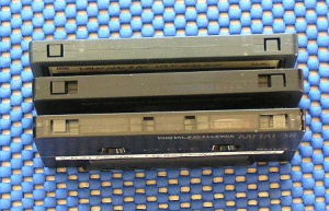
The breakable tabs are for write protection - prevents recording once removed.
Has effect on
- bias (e.g. metal types need more energy)
- EQ
The notches on the cassette can make players/recorders detect this,
though it's also frequently still a switch.
Some fancy recorders also let you fiddle with the amount of applied AC bias,
because too little makes for more distortion, and too much means less high-frequency response(verify)
On azimuth
The positioning of the head relative to the tape matters, in all directions.
When mounted in a machine, most directions (distance to tape, roll along tape) of a head are fixed and/or well controlled.
Azimuth ends up being the main one you may need to fiddle with.
Basically there is one screw that pushes one side of the head across the tape.
- the larger effect is that the head can be to the side of the tracks, sideways across the tape
- when it's mostly right it also matters slightly in that if it's particularly rotated, you get a very small delay between tracks, which if mixed works out as comb filtering in the high frequencies
For combined-R-and-W heads, misalignment means general tapes will sound worse here, and tapes recorded on it will sound worse elsewhere, but tapes used within this one systems will seem to mostly perfect.
For separated R and W heads you have different combinations of reads fine, records poorly, "other person's recordings work differently".
You can always adjust your head for a specific tape, and if you have a factory-recorded tape, for tapes in general.
You can e.g. count the screw-turns it takes to go from equally bad to either side, and then aim for the middle.
This works decently, though isn't overly precise.
There is a more precise method if you can forcibly mix the channels to mono, as the phase effect difference creates the comb-filtering-like in the higher frequencies, which gives a narrower optimal position where it audibly sounds better. So basically find any factory-recorded tape (see e.g. second hand stores). (Metal tapes are slightly better for this purpose due to better high-frequency response(verify)).
The tiniest drop of locktite may be a good idea to fix it in place for longer.
http://www.endino.com/archive/cassettes.html
For the electronic fiddlers
Playback is a magnetic field carrying baseband audio, so you can play with this pretty easily, and for low-fi it doesn't have to be precision engineered either, see e.g. https://www.youtube.com/watch?v=MMD-d-1erk4
But you may care to do it a little better than that.
The minimal circuit for playback is mostly an op amp, both for the voltage gain to line level, and as a buffer.
Playback amplification may well also equalize, in which case you'ld like to add a filter via a few more resistors and capacitors. Look for tape head pre amplifier circuits', and know there are ICs to help. https://www.youtube.com/watch?v=wn772K9cm9E
Recording is more complex.
The recording head's inductance matters (affects frequency response, you basically have to adjust for that) and recording current matter, as does the bias current, as does keeping the bias away from the source. (you can, alternately, mix the bias in with the signal before amplification, though this needs better amplifier specs)
See also:
Reel to reel tape decks
dcc
https://en.wikipedia.org/wiki/Digital_Compact_Cassette
DAT
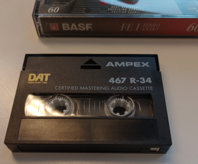
DAT (Digital Audio Tape) was one of the first digital audio recording products, introduced in 1987.
It recorded audio onto magnetic tape with a helical head (like video recorders), for more data density.
Digital audio recording wasn't unique at the time (there were some niche systems at the time that recorded digital audio e.g. onto video tapes), but DAT was originally intended for more general use. ...which it never did, probably for a good part due to legal action from the RIAA, but also in part because it was expensive.
For some historic context, audio CD was released a year or two before DAT was;
Where CD seemed poised to replace vinyl,
DAT (and/or minidisc) was perhaps intended to do the same for analog compact cassette tapes.
DAT never took off at home or to sell albums, though.
Lobbying and legal threats from the RIAA probably had a lot to do with that - RIAA was afraid that an easy recordable format would kill their sales.
That, and the setup was fairly pricy.
So DAT ended up mainly used as a tool within radio and the recording industry, and that use went away when recording studios moved to more convenient formats - like solid state recorders, and computers. It was an seemingly still is used in more professional film/video recording, presumably in part because you can write out the same timecode you used on video, and avoid a lot of searching later.
Technically
- helical scan head
- also implying the tape is always on the head, and could always be read during seeking
- and you can listen while seeking (though that sounds like a garbled version, not a high-pitched version like in analog tape).
- and players could assist finding pieces of silence/audio
- timecode - which made it practical to record distinct fragments in a somewhat non-linear way
The on-tape format is not something most of us ever deal with, or want to.
At best we care about the digital input and output, which due to the year was typically AES/EBU on earlier devices (not the SPDIF(verify) we now know, but the two are closely related).
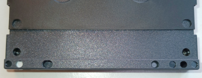
On the back of the tape are a bunch of holes-or-not.
- One of them (also a door on the front, often white plastic?(verify)) is write protect (When the door and hole is open, it is write protected)
- The one beside it and the cluster of three on the other side mark the length (and implicitly some part of the type) of DAT/DDS.
- The two nearer the center seem to be alignment.
DAT metadata
SCMS
DDS
Digital Data Storage (DDS) is DAT tape extended to be used for computer backups.
The first generation of DDS tapes were basically just regular 60-meter DAT tapes,
had the same roughly-1.3GB worth of storage on that tape,
and DDS hardware was mechanically quite close to DAT.
Later DDS variants increased length, and density, eventually up to 160GB.
There are 7 generations of DDS, and there are backwards compatibility details to consider.
(This (and other backup tape formats) have mostly been replaced by LTO, which has been around for a while but is still very much relevant, because the price-for-capacity is better than platter or flash.)
Is DAT and DDS the same tape?
The 60m DAT tape versus first generation of DDS, 60m DDS tape? Basically yes.
It's the same mechanism, and it's just data, the use of the tape is basically the same. Though the interpretation of that data is different, you could use them for either.
Some DDS drives were capable of reading audio off DAT, though it seems few people ever did that.
Note that the tapes are used a little differently.
DAT is often used accessed in a mostly-linear way (long recording, long playback)
DDS seek around more frequently, using it more intensely. Which wears out tape a little faster, which seems to be why people say DDS must surely be built to a higher standard. I'm not how true that is, and how much of it is still confirmation bias and such. But it is a reason to consider avoiding used DDS tapes for DAT.
So can I use DDS tapes in my DAT machine?
tl;dr: If you stick to 60m (1.3GB) DDS-1, yes. Longer isn't guaranteed - 90m might work, longer may not.
You can get into backwards compatibility and pitch and other specs, but probably me main reason is mechanical:
DAT's motors only have the torque to deal with DAT's 60m of length (DAT never changed(verify), DDS did).
Professional decks may have more leeway here when they're a little overspecced, and because of DAT's history, many decks are relatively professional, so YMMV and you may be fine with 90m DDS-1, DDS-2 and maybe DDS-3 - but you should really expect DDS-3 and later are out.
Like in reel-to-reels, a good test is to rewind and forward it completely - because fast forward (unlike playback) is constant rotational speed so this makes the highest demand on the motor torque. If feeding it through like that doesn't struggle throughout the tape, then it's probably fine.
Strategies of using tape
Linear
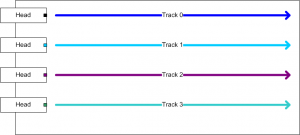
In linear tape, information on the tape is in long lines, dragged past the heads.
In analog audio tape, the strength of the stored magnetic field becomes the strength of the signal you get out, without any added translation.
Do an image search for magnetic view audio tape if you like more visuals.
The most basic tape might use much of the width of the tape for a single signal - for comparison, not entirely unlike a magnetic wire recorder, but we then figured that we don't need much width, and could store multiple tracks.
That said, if there are multiple tracks, most linear tape designs end up with a bunch of separation - so that the tape doesn't have to be positioned too precisely. (Yes, you could put things closer together - linear serpentine does exactly that, but it makes the tracks thinner and harder to find reliably. It's a lot easier to wider tracks, and works out as cheaper to make all parts involved.)
Which means we're not using all that much of the mangetically available area.
It also turns out there is an upper limit to how well tape magnetizes a fast-changing signal.
The rate in change (whether used for data or for the maximum audio frequency you can represent) is limited,
primarily by the tape's mechanical speed.
For audio, our demands work out at a mechanically reasonably low tape speed when you use it this way - consider that cassette or reel tape can easily store 60 minutes.
But we have things with much higher bandwidth requirements for a long time.
In particular video. Or data backup.
Sure, we could pull the tape past that much faster, but that becomes mechanically impractical for a few different reasons.
Just how much faster you need for, say, video is impractical, so people looked at other methods.
Multitracking
One is making it wider and adding more channels alongside each other.
In audio you could call them completely separate, some methods said you should consume all of them together somehow. Say, stereo cassette tapes were essentially four tracks: left and right one way, left and right the other way.
8-track has eight, one way.
Reel to reel tape exists in multitrack variants that give you amounts in the 4..24 range (the last only on chunky 2" tape), but the upper range is already pricy (and starts to approach the difficulties linear serpentine was aimed at).
This works fine up to a point, though it puts higher requirements on aligning the tape correctly. If you don't, then in audio you lose quality, in data it just stops working before that.
Note that there are few systems that consume all tracks at once.
most multitracking only records or reads a few tracks at a time.
E.g. 8-track players physically shift the head sideways onto another track, cassette tape has to be turned around to put the other tracks onto the head correctly, multitracking has similar tricks.
If you squint, these are sort of a manual variant of linear serpentine system - you can't read everything at the same time (and you don't want to).
- An 8-track can read two of the 8 tracks at a time,
- A cassette tape deck (with a stereo recording) reads two tracks at a time; you get the other two by turning it over.
- Reel to reel has had more variants over time, but the most popular(verify) seems to be the same as cassette tape: four tracks, two at a time and flipped over.
Helical scan
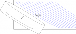
Another way is helical scan, as used e.g. in most video tape, and in DAT/DDS. These systems place tracks on diagonal strips. This doesn't increase the density much over many-track, and is more complex head construction (angled head, requires tracking, head spins faster to get more effective speed than the tape's mechanical speed) but what comes out is a single high-rate thing (a factor ~150 over audio tape, and still a few factors over most many-channel(verify)) and you wouldn't have to separate and reassemble your signal because that's the head's job.
https://en.wikipedia.org/wiki/Helical_scan
Tapes for data backup, practical things like physical size of the archive matters.
Both helical and linear are now roughly at their engineering limits and unsurprisingly their density is similar, and the reasons to choose one over the other for e.g. backup are largely pragmatic ones - while for other uses (VCR, DAT, analog audio) they are mostly historical.
Linear serpentine
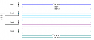
With that wowed introduction of helical scan, you might assume linear is dumb, helical is best, and e.g. the LTO backup tape that is still in use must be using helical.
Actually, LTO uses linear serpentine, which is a fancy way of saying:
- it uses so many tracks that it has more tracks than it has heads
- it has a way to move the heads to specific tracks (with precision - the width of tracks is on the order of dozens of micrometers)
The engineering is a lot more precise than in classical linear tape, and you need to feed the tape past the head multiple times to even read, or write, all of its data, but if you care about the most density per tape, this works out better than helical scan (and much better than linear).
For some reference,
- LTO-1 was 8 heads and 384 tracks
- LTO-8 is at 32 heads and 6656 tracks
Yes, that means writing a tape to capacity actually requires, depending on the LTO version, something between fourty and a hundred-fifty passes of the tape's length.
So noo, this is not at all a random-access system, and has rather high latency. Yet for most backup and archival uses, that's rarely an issue, the price is hard to argue with, and it's also engineered to last longer than at many other common storage media.
Floppy heads
Floppy heads are conceptually quite similar to tape heads.
Roughly compatible, even. this neat audio-floppy hack wires the floppy head to a cassette tape device.

Note the read/write slit leads the two erase slots to the side
There are differences, primarily in the way it deals with tracks.
It seems typical floppy heads:
- on the track: read-write gap
- to the sides: tunnel-erase gaps (well, typically tunnel style. There also seems to be a straddle type, which is alongside rather than behind, and requires slightly different timing)
- these tunnel heads are not strictly required, but were practically quite useful:
- wipes the spillover that may appear between tracks. Makes for more stability. Also helped interoperability a bit - without this, reuse of disks in different standards would be likely to react to off-track magnetization that was old data but would work as noise (and could not be altered in that other-type drive because it's off-track)
Note that where tape erase and write at the same time, floppies do this in two passes:
- erase the sector (stronger amplification on the R/W head)
- write the sector (regular R/W amplification)
Perpendicular recording existed, but was never very common (used e.g. in 2.8MB (4MB raw) floppies).
This required the magnetic medium to have higher coercivity,
and apparently implied a pre-erase gap leading the read/write gap (like how erasing works in tape. Not sure whether this was necessary or just a design decision).
It seems the R/W heads are typically a center-tapped coil (i.e. coil pair on one core).
I'm guessing this is because bit values 0 and 1 are magnetized in one direction or the other, and it's slightly easier/cheaper to drive this way. (verify)
A read is probably across the pair, because stronger signal. (TODO: read up, this must be moderately common knowledge)
Opening a head and seeing two coils is usually the RW part, and the erase part(verify) (the center tapping of the former is hard to see)
As such, you typically have 5 wires and they'll be:
- shield - grounded, and not connected to other parts at the head size (other than large bits of metal around it - also making it easier to find this one with a multimeter)
- common between all coils
- R/W 1
- R/W 2
- Erase
Making a table of all possible combinations's resistance (just because they're different lengths of wire) typically helps find which is which, though you'll be thrown by there possibly being a diode and resistor in there.
The best explanation on how writing bits works that I've found sits in a Shugart service manual (SA400).
See also:
- http://ohlandl.ipv7.net/floppy/floppy.html
- http://ohlandl.ipv7.net/floppy/DS011332.pdf
- http://www.osiweb.org/manuals/MPI_B51-B52_Product_Manual.pdf
- https://nfggames.com/X68000/Documentation/Floppy%20Drives/Shugart/SA400%20Minifloppy%20service%20manual.pdf
- http://www.retrotechnology.com/herbs_stuff/drive.html
- http://jlgconsult.pagesperso-orange.fr/Atari/diskette/diskette_en.htm
- https://cdn.hackaday.io/files/20185863595040/NEC%20FD1036%20Floppy%201985.unlocked.pdf
- restoration/DIY (has some practical notes)
- https://www.retrohax.net/commodore-1541-floppy-drive-fixing-chaos/
- http://deramp.com/downloads/altair/hardware/8_inch_floppy/Drive%20Restoration%20Drive1.pdf