Electronics notes/Capacitors: Difference between revisions
mNo edit summary |
|||
| (2 intermediate revisions by the same user not shown) | |||
| Line 1: | Line 1: | ||
{{electronics notes}} | {{electronics notes}} | ||
===Intro=== | |||
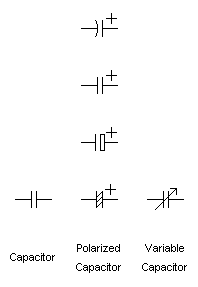
[[Image:Capacitors circuit symbols.png|thumb|198px|right|The symbols used in circuits]] | [[Image:Capacitors circuit symbols.png|thumb|198px|right|The symbols used in circuits]] | ||
'''Capacitors''' (regularly abbreviated as '''cap'''s) take an electrostatic charge, which (ignoring leakage) will remain until discharged. | '''Capacitors''' (regularly abbreviated as '''cap'''s) take an electrostatic charge, which (ignoring leakage) will remain until discharged. | ||
| Line 31: | Line 29: | ||
===Some theory and behaviour=== | ===Some theory and behaviour=== | ||
<!-- | <!-- | ||
Capacitors are two conductive plates separated by a non-conductive region, the dielectric. | |||
...and (except for a not-very-efficient-at-all physics class model) | |||
so tiny that you can't see it. | |||
There are a number of different capacitor designs, | |||
varying the dielectric materials, | |||
plate shape/area, | |||
and more (varying in price, | |||
max voltage rating, | |||
maximum charge, | |||
implicit inductance, | |||
and more. | |||
{{comment|(The physical makeup is not important in generic use, and even in moderately specific specs you're often looking more at specs)}} | |||
While ideal capacitors are almost ''completely'' characterized by their capacitance, | |||
real-world aspects means you often sometimes care about further specs. | |||
| Line 46: | Line 56: | ||
The SI unit of capacitance, the Farad, indicates the a charge in coloumb (Ampere-seconds) a capacitor will accept for 1 Volt across it. | The SI unit of capacitance, the Farad, indicates the a charge in coloumb (Ampere-seconds) a capacitor will accept for 1 Volt across it. | ||
One Farad is actually a ''lot''. Capacitors used in most electronics are in the range of microfarads (10<sup>-6</sup>), nanofarads (10<sup>-9</sup>), or picofarads (10<sup>-12</sup>). | One Farad is actually a ''lot''. Capacitors used in most electronics are in the range of microfarads (10<sup>-6</sup>), | ||
nanofarads (10<sup>-9</sup>), or sometimes picofarads (10<sup>-12</sup>). | |||
| Line 54: | Line 65: | ||
uF and mF capacitors can be pretty chunky, at few-dozen to line voltages, | uF and mF capacitors can be pretty chunky, at few-dozen to line voltages, | ||
Above one farad we'd call it supercapacitors or ultracapacitors, | Above one farad we'd call it supercapacitors or ultracapacitors, | ||
and much too large for most resonating/filtering uses. | |||
At uF at line voltage, or mF at PCB voltage, capacitors start being chunky things, finger-sized and larger. | At uF at line voltage, or mF at PCB voltage, capacitors start being chunky things, finger-sized and larger. | ||
Chunkier capacitors are often electrolytic designs, because those are easy/cheap for energy storage, and it | supercaps tend to be moderate to large at ''any'' useful voltage. | ||
Chunkier capacitors are often electrolytic designs, because those are easy/cheap for energy storage, | |||
and for that use it rarely matters that they are less precise/efficient. | |||
| Line 66: | Line 84: | ||
'''Imperfections that deviate from ideal capacitors.''' | '''Imperfections that deviate from ideal capacitors.''' | ||
Real-world capacitors (and real-world use of them) deviate from the ideal model. For example: | Real-world capacitors (and real-world use of them) deviate from the ideal model. | ||
* capacitors have inductance (varying with design), which matters to how well they can be used in high-frequency applications | For example: | ||
* real capacitors have inductance (varying with design), which matters to how well they can be used in high-frequency applications | |||
* capacitors have a small leakage current. It's negligible for many uses, though for battery replacement you'll probably want specific designs that minimize it. | * real capacitors have a small leakage current. It's negligible for many uses, though for battery replacement you'll probably want specific designs that minimize it. | ||
* | * a real capacitor '''can have polarity''', in that one lead should always have a potential larger or equal to the other. Reverse-biasing it {{comment|(...with more than perhaps a volt (for most capacitors))}} will cause the capacitor to fail. | ||
** in particular, electrolytic capacitors are polarized | ** in particular, electrolytic capacitors are polarized. Reverse biasing these with enough voltage will cause an electrochemical reaction in the electrolyte, causing it to heat, expand, vent, and quite possibly for the cap to then short out. | ||
** For other capacitor designs you may see nothing more than that the capacitor is now shorted, effectively a bit of wire. | ** For other capacitor designs you may see nothing more than that the capacitor is now shorted, effectively a bit of wire. | ||
Revision as of 19:32, 29 March 2024
Intro

Capacitors (regularly abbreviated as caps) take an electrostatic charge, which (ignoring leakage) will remain until discharged.
When you put DC across them, they charge to that voltage.
They work as a sort of battery - with tiny capacity, but enough for a number of practical uses.
When you put AC across them, limited charging speed means they work more like frequency-dependent resistors, as in oppose some frequencies more than others, which is why they help build signal conditioning, noise reduction, filtering, and resonant circuits.
Some theory and behaviour
Charging and discharging
See also:
Capacitor marking
Rating considerations
Voltage
You'll often know the maximum voltage a capacitor will be exposed to, though you may wish to consider your circuit's ripple current, peak current, fault current, possible voltage reversal, and more.
The voltage spec seems a nominal one, in that it can probably handle more, but you may shorten its lifespan, and with significantly more you will make it fail.
Temperature (spec / behaviour)
Dielectrics / types / designs
Electrolytic capacitors (type)

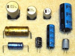
- polarized - reverse biasing these will cause an electrochemical reaction in the electrolyte, causing it to heat, expand, vent, and likely short in the process. The common cylinder shape has indentations on the top that will bulge and fold open (a safety feature, and one that makes failed electrolytic caps easy enough to identify)
- higher inductance than many other types, so not so useful for high-frequency applications
- cheap, so common wherever the frequency or stability limitations are not a problem
- often can-shaped, and regularly black, grey, blue, and with a stripe indicating its negative lead
- Capacitors with more than ~1µF are regularly electrolytic capacitors because of cost. Other types are also used, but often when electrolytic's polarization or lower stability is a problem.
Ceramic capacitors (type)

http://en.wikipedia.org/wiki/Ceramic_capacitor
Tantalum capacitors (type)
- http://images.google.com/images?q=tantalum%20capacitors
- http://commons.wikimedia.org/w/index.php?title=Special%3ASearch&search=tantalum+capacitor
- http://images.google.com/images?q=SMD+tantalum+capacitor
Silver mica capacitors (type)
http://en.wikipedia.org/wiki/Silver_mica_capacitor
Plastic film
See also (types)
Variable Capacitor (design)
Adjustable capacitors, often looking similar to potmeters (and frequently like trimpots).
Specializations
EMI/RFI suppression (spec)
Pulse capacitor
More applied
Gimmick (design)
Bypass capacitor (application)
De-coupling and coupling capacitor (application)
Power supply filtering (application)
Lowpass filter (application)
Signal generator (application)
Capacitive dropper (application)
See Electronics_notes/Changing_voltage#capacitive_dropper
Motor capacitor (application)
See also
- http://www.educypedia.be/electronics/capacitorstypes.htm
- http://www.satcure-focus.com/tutor/page6.htm