Common plugs and connectors
Yes, this is largely biased to the stuff I deal with.
Ideally 'common' is true enough. Suggestions are welcome.
Mixed use (analog, digital, home electronics, audio)
TRS (Tip, Ring, Sleeve) and variations
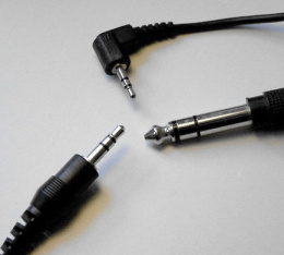
2.5mm TRS plug (top)
6.35mm (1/4") TRS plug (right)
'TRS' may be clearer when distinguishing it from plugs in similar use, but the everyday names we use are more specific - and somewhat regional.
The 3.5mm is often known as headphone jack, stereo jack (if TRS, or mono jack if TS), mini jack, or 3.5mm jack, and sometimes things like mini-phone.
The 6.35mm was classically called phone connector (2-lead, TS) though perhaps the largest use today is guitars.
The history of plugs like these is complex[1], and there are some leftovers today that use less usual variants.
But what you're most likely to meet is primarily:
- The 1/4" (which is 6.35mm precisely)
- originates from the design of the first telephone exchanges(verify), which is why this (particularly the mono, TS variant) is also called a phone connector
- These days they are mostly seen in audio use, seemingly as something not so easy to break
- used for guitars, pro line level (balanced or not), and sometimes for consumer headphones
- 3.5mm
- Americans often refer to it as 1/8"
- best known for three-band (TRS) in headphones for stereo sound, then often referred to as audio jack, mini-jack, jack plug, stereo plug, and others. (Sometimes phone connector but that suggests the 1/4" one)
- often carries consumer line level audio signals, or consumer microphone level when it involves microphones (often electret)
- 2.5mm
- Americans sometimes call this 3/32"
On units - The 1/4 size is standardized in inches because of its phone network origins(verify),
- ...while 2.5mm and 3.5mm are standardized in millimeters, and I do believe always manufactured to mm sizes, so the inch figures are names, not measurements:
- taking 3.5mm and calling it 1/8" is 10% away from the actual size (3.5mm is 0.138", not 0.125")
- taking 2.5mm and calling it 3/32" is 5% away from the actual size
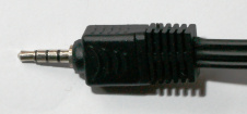
TS, TRS, TRRS, etc.
The original 1/4" had two contacts, so had a tip and sleeve (TS).
It grew more bands over time, so e.g. 3.5mm is frequently seen in TS, TRS, and occasionally TRRS. TRRRS exists but is rare.
3.5mm TRRS is
- is probably mostly associated with having headphones that include a microphone, around smart phones.
- has some other uses, like carrying audio and (composite) video on one plug (e.g. on raspberry pi)
Not-really-compatible variants
A few synthesizers (Buchla and clones(verify)) use tini-jax which is .141" (~3.6mm) and basically incompatible with 3.5mm
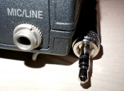
I've also seen a variant of 3.5mm that can be screwed down, which is quite useful for use on stage where you don't want a yank to stop the music - yet e.g. in the image on the right the screw-thread ring on this plug doesn't pull back so this particular plug won't plug properly into most other 3.5 sockets.
See also:
TRS pinout
Pinout
Depends on the use. Things I've mostly dealt with:
- 3.5mm TRS in consumer stereo sound (unbalanced)
- tip: left
- ring: right
- sleeve: ground
- 3.5mm TRRS for headphone, mic and/or buttons
- 3.5mm TRRS combining audio and analog video, such as
- iPod's AV cable
- tip: left
- ring: right
- ring: ground
- sleeve: video
- raspberry pi audio+video (same pinout)
- there are pinout variants of this.
- It's handy to have adapters with RCA, in that sometimes you can get around variations by plugging things differently. But don't count on it.
- iPod's AV cable
- 6.35mm TRS headphones (unbalanced, same as 3.5mm consumer but sturdier; often with adapters to 3.5mm)
- tip: left
- ring: right
- sleeve: ground
- 6.35mm TRS balanced audio (stage/pro audio)
- tip: hot
- ring: cold
- sleeve: shield
- 6.35mm TS unbalanced audio (stage/pro audio)
- guitar, instruments (unbalanced)
- tip: signal
- sleeve: ground
- 6.35mm TRS: mixer effect inserts (unbalanced)
- tip: out
- ring: in
- sleeve: ground
- Music_-_studio_and_stage_notes#Insert
Note that in many uses, sleeve is ground (shield where applicable)
Headphone buttons
The buttons don't need extra wires in a TRRS plug because they'll be using different resistor values between mic and ground pins.
For Android[2]:
  0..70  ohm   Function A, play/pause/takecall
110..180 ohm   Function D, typically voice commands
210..290 ohm   Function B, volume up
360..680 ohm   Function C, volume down
(The impedance of the microphone itself is considerably higher, and sense-wise acts as the default)
For Apple,
~0 ohm is play/pause/takecall
Everything else seems to be proprietary signaling, which allows them to add functionality over time. And piss of imitators and DIYers.
RCA
-
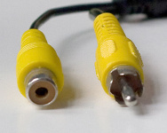
RCA socket and plug
-
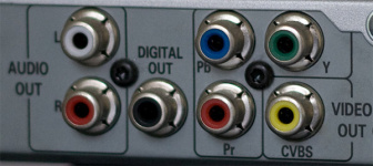
Bunch of RCA sockets (for two types of audio output and two types of video output)
Used for audio, video (often composite, now also component), some simple data (like non-optical digital audio)
Named for its introduction by the Radio Corporation of America.
Other names include cinch connector, phono connector, and some odd ones out like the Dutch calling it a tulpstekker (after tulips, because of course).
See also:
DIN
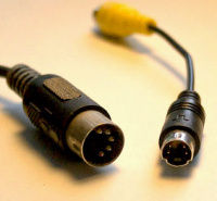
Right: 4-pin mini-DIN - see the next section
DIN refers to a whole standardization body. Only with a number does it refer to a specific standard, of which there are many'. Which includes connectors.
But no one remembers those numbers, so we say "DIN connector" and leave it to context.
Around consumer devices it most commonly refers to the members of a specific series of circular plug/sockets of similar design, that have a 13.2mm-diameter round metal friction locking shield. (These come from at least five different DIN standards, though it seems these original DIN standards are out of print, and you now want to read IEC 60130-9, which also expanded the series (verify))
This set includes:
Being an existing, relatively sturdy, relatively versatile, and relatively cheap style of connector, these once saw a lot of varied use, be it digital (e.g. MIDI, AT keyboard connector), audio/video (e.g. tape decks, microphones), and sometimes power.
Many of them were fairly specific to brands or devices (e.g. Commodore 64 uses 7-pin for power, and 8-pin (5-pin in a few early models) for audio and composite video).
Many such uses have since grown more specific connectors.
Which is probably good, to avoid smoky mistakes from too many distinct uses sharing a plug.
The only one that survived a lot longer in wide use is MIDI, with its 180 degree 5-pin din plug.
Other DIN you may well have seen includes:
- DIN 41529: 2-pin, historically seen in loudspeakers, though I've also seen them used for low voltage lighting
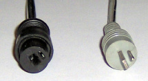
DIN 41529
- TODO: more
Note that some of these have since been effectively moved into international (IEC) standards.
See also:
- https://en.wikipedia.org/wiki/DIN_connector#Circular_connectors
- http://www.muzines.co.uk/articles/interconnect/2828
Look a bit like
Mini-DIN
Mini-DIN is a similar-looking variation also from DIN ((verify), I can't easily find the number), with a 9.5mm round metal shield. Additionally uses plastic slots that makes plugging into other variants hard without a hammer.
-
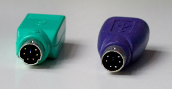
PS2 mouse and PS/2 keyboard (here on adapters from USB) (6-pin mini-DIN)
-
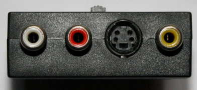
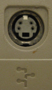
S-video on the back on a SCART adapter (4-pin mini-DIN)
-
Apple Desktop Bus (4-pin mini-DIN)
Probably best known for
- PS/2 keyboard/mouse (6-pin)
- S-video (4-pin)
Other uses include audio, video, some communication, and some fairly one-off video card adapters back when analog video was still a thing we wanted.
I've also seen some used for power.
You should assume each connector has multiple, unrelated uses before you plug something in.
See also:
Mini-DIN lookalikes

There are a number of have the same 9.5mm housing as mini-DIN, but are not standardized or approved by DIN.
Some are designed to be compatible with specific standard mini-DIN (e.g. to have a video card socket that accepts both standard S-Video plug but also its own connects-more-stuff variant).
Others are designed to be specifically incompatible with standard mini-DIN.
Video cables/plugs
Composite video
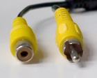
Composite video (not to be confused with component video).
Usually plugs around in a one-yellow-RCA-plug way, sometimes using a BNC plug.
Carries Y, U, and V signals with sync pulses, and is also easy to broadcast - it is almost entirely the same as analog TV's format.
...in a baseband way, without modulation.
The main upsides to composite is probably that it is easy to transfer video between devices with a single, simple, common plug.
The main downside is that it somewhat susceptible to various visual artifacts, including noise/interference, dot crawl.
It arguably varies mostly with the quality of the encoding/decoding hardware, which indeed has varied, and which is internal so you have no control over.
The only thing you could change is cable length. Shorter cables sometimes help a little.
Composite video is sometimes called CVBS. Depending on who you ask, that's short for
"Color, Video, Blank and Sync",
"Composite Video Baseband Signal",
"Composite Video Burst Signal", or
"Composite Video with Burst and Sync".
RF modulators
Being so similar to TV signals, and there once being a time at which TVs only took antenna inputs.
So there was a time at which devices (like video tape recorders, early game consoles, and and some early computers) modulate their video a signal onto a local video channel, to then be decoded again by the TV. And this is, often a way to deliver what before and after that is more or less composite.
S-Video

S-Video (also Super Video or Separated Video, and also sometimes called Y/C) carries luma (Y) and chroma (C) signals on separate wire pairs, using standard 4-pin mini-DIN plugs.
It carries the same information as composite video, but avoids shoving the Y and C information together onto one wire.
This will be better than the cheapest implementations of composite -- yet with good hardware and ideal conditions for composite, S-Video is no better than composite.
S-Video-to-Composite-video converter cables can just join the wires (although this may mean the colors are less saturated - something about the voltage amplitudes of these two signals?(verify)).
- ...and for the same reason you can not use that same wire to go from composite input to S-Video output (connecting it anyway puts the mixed Y+C channel on both the Y and C pairs, which the S-video decoder will partly understand, but will usually results in a black and white image(verify))
S-Video-like

You may find some Mini-DIN_lookalikes that resemble the 4-pin mini-DIN S-Video plug. This includes:
- a 9-pin variation called VIVO (Video In Video Out), seen on video cards, that allows S-Video in, S-Video out, component out, and composite out.
- I've seen some video cards come with a 7-pin plug. This is rarely a standard mini-DIN plug, and often has its plastic slot in the same place as on the 4-pin DIN plug, but wider, so that the video card socket will accept a standard S-Video plug, and also the plug on the cable supplied with the card which uses the extra pins to carry, usually, another type of video (often composite video, sometimes composite video).
- a different 7-pin connector (standard mini-DIN) used on some professional (VCR) kits
Component video (YPbPr)
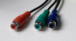
Component video (not to be confused with composite video) could in theory refer refer to any system that sends video in multiple separated channels.
...but it quite usually refers specifically to a Y,Pb,Pr setup, typically on three RCA connectors (and sometimes on other things, like D-terminal), and for YPbPr these connectors are frequently red, green, and blue.
- The green plug carries the Y signal (Luma),
- the blue the Pb (blue minus yellow)
- and the red the Pr (red minus yellow) signal
...not to be confused with RGB video, which also exists, in multiple forms (and which you could call component video in the wider sense)
See also Color_notes_-_color_spaces#YCbCr_and_YPbPr
SCART

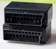
SCART (a.k.a. Euro AV, EIA Multiport) combines a bunch of analog audio and video formats used by various common plugs, making it somewhat easier to connect various common home devices.
SCART can carry:
- Mono/Stereo Audio, both ways
- Composite video, both ways
- S-Video may be supported both ways, but isn't always implemented
- RGB (on newer hardware, by re-purposing some wires, so both ends need to support and both to specifically this (ab)use)

You can easily find adapters to one or more specific things, like RCA audio, composite video and/or and S-Video, and sometimes versions with a switch that selects whether you want to use the converter plug to act as input or output.
RGB is higher quality, but was non-standard and added later
- has to be supported by both sides
- can also not be used at the same time as S-Video output
- is only intended for one direction, player-to-display travel
- so is supported primarily by some more modern TV sets (receiving role) and recent media players (sending role)
- supporting players may only send RGB once you explicitly configure them for it, for compatibility reasons.
See also:
- http://en.wikipedia.org/wiki/SCART
- EN 50049-1
VGA

VGA technically refers to Video Graphics Array, a specific video card from the late eighties that set a graphics standard, including the 640x480 resolution (though any VGA card already did more than that)
As other graphics cards appeard, it came to refer to the connector used (DE-15) and the way it carries image signals, which stuck around for a long time and which supports much higher resolutions (over short cables).
While it's a 15-pin connector, there's a lot of redundancy in there. Most important are five signals, and ground:
- hsync
- vsync
- red pixel data
- green pixel data
- blue pixel data
- ground
Four further pins were reserved for DDC (Display Data Channel) to help PCs identify monitor capabilities. DDC saw a few different schemes and protocols over time (including pulldown resistors, one-directional serial, and I2C). one pin is 5V to power the EEPROM used in some of these schemes, but is otherwise unused.
On ground: Pinouts may show the center row all grounds and interconnected, but in most cables these are individual paths, a separate ground - e.g. red and 'red ground' in a twister for lower interference(verify), etc. (in this regard, VGA may be theoretically better at analog signals than DVI-A because DVI-A shared one analog ground between r,g,b)
VGA made sense when monitors were cathode ray tubes and their scanning beam made them all-analog in nature - you had to convert it to analog somewhere, and they chose to do it in the graphics card.
Connecting flatscreens via VGA makes less sense electronically: We have a digital image with discrete pixels in the PC, the eventual screen pixels are discrete, but we convert it to analog, to carry as analog, then convert analog back to digital. Yes, the timing is usually pretty good, but it's an unnecessary intermediate step, asking for mild analog signal losses, and a little ghosting and similar such issues, particularly for the faster speeds required for higher resolutions and/or longer cables. We moved on to digital communication for our monitors for a reason.
(I see pages being cautious about 1080p but we've had resolutions higher than that since the nineties, and it's fine pushing through 1080p60 through any but the cheapest cables. Yet being analog, this is also roughly the point it starts degrading. Higher resolutions quickly start demanding ~300MHz of bandwidth, which is fine over a short good quality cable, and conversion - though neither are guaranteed, sure)
Also, it can be a fun to mess with those analog voltages - see also VGA hacking
D-Terminal
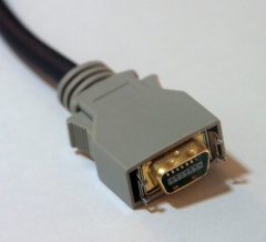
D-Terminal (not to be confused with D-Subminiature a.k.a. D-Sub) is probably most common in Japan, and seen elsewhere mostly in specific applications, e.g. digital satellite tuners.
The wires carry component video, and also signal lines that use logic-level voltages to signal the video's resolution, ratio, and whether it is interlaced/progressive.
Has five modes, carrying analog 480i through 1080p, varying with the actual devices,
and sockets may be labeled with D1 through D5 as indication of what a device is capable of, which seems to include:(verify)
- D1 480i (525i): 720×480 Interlaced
- D2 480p (525p): 720×480 Progressive
- D3 1080i (1125i): 1920×1080 Interlaced
- D4 720p (750p): 1280×720 Progressive
- D5 1080p (1125p): 1920×1080 Progressive
Breakout cables to component video over RCA and BNC exist.(verify)
I'm not clear on how/whether this is related to (mini)-centronics.(verify) - might this effectively be mini-MDR14?
See also:
Digital video cables (high speed and/or uncompressed)
Such as:
DVI

On digital and/or analog
DVI can carry both analog and digital video, but specific wires and interfaces can choose to do just one.
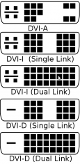
There are roughly four variants. To tell them apart,
- look at the plate on one side
- if there are pins around that plate (red in the pinout image on the right), the cable can carry analog video.
- if the nearest 3x3 pins is a full block, it can carry digital video
- it's called DVI-A if it can carry only analog
- it's called DVI-D if it can carry only digital
- it's called DVI-I if it can carry both
- If everything is one solid block of pins (that is, includes the blue pins in the image on the right), it can do dual-link digital.
- If it's not full, it's single-link digital.
There are some other connectors that look roughly like DVI but are incompatible, such as:
- VESA P&D / M1-DA (an extension to DVI from VESA)
And two different many-pin connectors, often seen for many-monitor graphics cards, as each connector can be used for two monitors:
Needs an adapter for things like DVI or VGA (doesn't carry them directly). The absence of pin 58 in DMS-59 seems to be just for keying. It isn't used in LFH either(verify), so you can use DMS-59 cables where you would otherwise use LFH.(verify)
See also:
MiniVGA, MiniDVI, MicroDVI, Mini DisplayPort
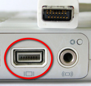
Mini VGA
- mainly seen in Apple hardware (mostly MacBooks) circa 2005(verify)
- not standardized, died out fairly quickly
- replaced by Mini DVI (which could also go to VGA) and MiniDisplayPort (which does even more)
- http://en.wikipedia.org/wiki/Mini-VGA
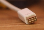
Mini DVI
- mainly seen in Apple hardware (mostly MacBooks) circa 2005(verify)
- not standardized, died out after a while
- didn't really support non-Apple converters to VGA
- http://en.wikipedia.org/wiki/Mini-DVI
MicroDVI, again mostly Apple, was used on some Macbook Airs.
- confusable with USB ports.
- not standardized, died out after a while
- There are adapters to VGA and to DVI-D (not DVI-A or DVI-I(verify)).
- http://en.wikipedia.org/wiki/Micro-DVI
All of the above were discontinued circa 2010, in favour of Mini DisplayPort.
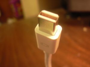
Mini DisplayPort
- Initially in Apple laptops, now adopted by VESA and used by other vendors
- There are converters to VGA, (Dual-Link) DVI, HDMI, Displayport, and probably more
- May also carry audio, may not.
- http://en.wikipedia.org/wiki/Mini_DisplayPort
Other Apple connectors

Intel and Apple developed Thunderbolt, which uses the same plug as Mini DisplayPort.
...which is intentionally backwards compatible.
But, for the same reason, also potentially confusing,
- It's a more generic bus like USB, but the expectations of such are probably still mostly monitor-y.
- so e.g. the same Apple monitor might do more on one laptop than another.
It's safe to connect and will display, but any feature beyond that won't work.
You can tell by the logo:
- monitor-like logo → Mini DP
- lightning bolt logo → Thunderbolt.
Note that Thunderbolt 3 uses the standardized USB-C (which is now entering general use),
so mini-DP-style thunderbolt is now sometimes referred to as Thunderbolt 2 connector.
This at least is expected to be a generic interconnect.

Thunderbolt is, by name, confusable with Lightning (introduced 2012, now being displaced by USB-C (slower than you might expect, possibly because of proprietary sales reasons)).
Lightning is the thin flat reversible plug with little strips of connector.
There are eight pins, carrying
- Vcc and Gnd (charging),
- two differential pairs that can carry USB (and has active adapters to HDMI, VGA, Audio, and apparently SD card reading).
It is almost exclusive to iPhone, iPad, iPod, and a handful of Apple accessories. Lightning replaced the earlier dock connector (and e.g. lightning headphones made sense to make where 30-pin dock headphones didn't really).
30-pin dock connector (since 2003, and mostly disappeared since Lightning in 2012).

which seems to carry:
- USB
- stereo audio in
- stereo audio out
- S-video
- FireWire
- Serial (used by iPod? 19200 baud?)
- pin that let accessories indicate roughly what they are, e.g. used for "please output audio into me" (verify)
- 3.3V
- 5V
- 12V (for firewire)
- various Gnd (separate for power and some of the signals)
(the connector itself seems to be a non-standard variant of JAE DD1. Apple seems to have intentionally made it hard to get, though you can e.g. still get some breakout boards)
HDMI

High-Definition Multimedia Interface (HDMI) [3]
Can carry digital video, and digital audio.
There are plug variants.
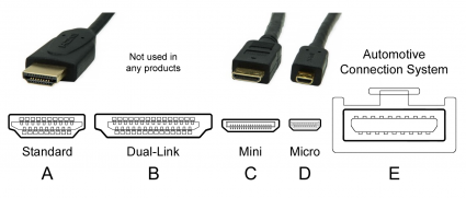
- Type A is by far the most common, what you usually use
- Type B has more data lines, designed for very-high-bandwidth applications, but never got used. DisplayPort now make more sense in practice
- Type C is the mini variant (meant for small/mobile devices)
- Type D is the micro variant (meant for small/mobile devices)
- seen e.g. on Raspberry Pi 4
- Type E is an automotive variant - locks in place, more resistant to moisture and dirt
- you can also get type A in a harness, giving similar features while being compatible with existing cables
(For computers it can be relevant that HDMI can carry DVI-D fairly directly - though this will probably only work if the DVI device supports HDCP (copy protection), because the HDMI side is likely to require it)
CEC (Consumer Electronics Control) is for simple commands between a set of interconnected devices, e.g.
allowing your TV remote to control some common functions of a set-top or DVD player, have a device turn the TV on and to it as a source, control volume, transfer a preferred device name, things like that.
CEC is mostly known under names like Anynet+ (Samsung), 1-Touch Play (Roku), and various names involving 'Link' (lots of brands).
Electrically it is a one-wire bidirectional serial bus, separate from HDMI communication so that everything but this can sleep, and is very slow (~400bit/s) because it doesn't need to be faster.
See also:
- http://en.wikipedia.org/wiki/High-Definition_Multimedia_Interface
- https://en.wikipedia.org/wiki/Consumer_Electronics_Control
DisplayPort
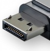
Digital transfer; can carry video, audio, data, and a little power (for adapters?).
Because it was aimed to be a replacement of HDMI, DVI, VGA, and things like FPD-Link, it was made with compatibility in mind.
The signaling is not directly compatible with DVI or HDMI, but adapters are not complex.
While VGA adapters have to be active, they can be powered through the DP cable (if short(verify), which most are).
Cable length
Specs say 2 or 3 meter max.
This is a cautious figure and decent cable quality may go a little longer, in part because it's only higher speeds that run into trouble.
But don't count on more than 10-20m, and then only for for lower(-data-rate) resolutions.
Active cables could go up to 15-30m at somewhat higher rates/resolutions in a more compliant, less fragile way. (Note that active cables must be connected in the right direction - passive cables don't care).
If you want more than that, you probably want fiber DP instead of copper DP (at high enough rates and distances, the issue is capacitance and sort of unavoidable).
A Dual-mode DisplayPort output (a.k.a. DP++) supports the use of an adapter to single-link DVI or HDMI. (a passive adapter in that the output itself already speaks the right thing, the adapter only changes voltages)
Without this, only an active adapter (something that does a conversion between different video formats inside it) would work.
Other conversion formats (e.g. to VGA) always require this.
Bandwidth
A single lane (differential pair) in a DP cable can be run at one of four speeds,
- 1.6GBit/s raw, ~1.3GBit/s data in RBR (reduced bit rate)
- 2.7GBit/s raw, ~2.1GBit/s data in HBR mode
- 5.4GBit/s raw, ~4.3GBit/s data in HBR2 mode (introduced in DPv1.2)
- 8.1GBit/s raw, ~6.5Gbit/s data in HBR3 mode (introduced in DPv1.3)
Cables made for higher speeds will often be 4-pair, which means:
- 4-pair HBR is ~8 Gbit/s (~10Gbit/s raw minus 20% coding overhead)
- 4-pair HBR2 is ~17 Gbit/s (~21Gbit/s raw minus 20% coding overhead)
- 4-pair HBR3 is ~25 Gbit/s (~32Gbit/s raw minus 20% coding overhead)
Your average monitor will just work on most any cable. Making 1080p fail on a short cable would take effort.
You would only care about these numbers if you use a combination of 4K, deep color, 120fps, and 3D, e.g.
- 3840×2160@120fps requires HBR2,
- 5120x2880@60Hz require HBR3
- multiple displays on a single port can be done
Mini-DisplayPort

Like it says - a smaller plug that carries DisplayPort.
Seen used on laptops in general, and Apples in general, for monitors
Also used on Apples for Thunderbolt (1 and 2)
See also:
GVIF
Gigabit Video Interface (GVIF), carried by a single twisted pair of wires, also allowing a data channel.
Plugs vary.
Used mostly in a few automotive uses, and then largely video-only. Up to 10 meters, up to ~2GBit.
(Not to be confused with GSIF, GigaSampler InterFace)
https://en.wikipedia.org/wiki/Gigabit_Video_Interface
UDI
UDI (Unified Display Interface) [4] [5]
Seems to never have made it out the door, apparently deprecated in favour of DisplayPort(verify)
SDI
SDI (Serial Digital Interface) is an uncompressed digital video (and audio) signal, originating around 1989 and to this day mostly seen in professional use.
Electronically:
- BNC connectors, coax with 75 Ohm characteristic impedance (which was the same cabling as analog video setups, which helped upgrades, but also some confusion)
- 800 mV peak to peak (but receiver can deal with lower, meaning in clean environments you could have maybe 300m runs of ~270 Mbit (SD-)SDI without repeaters - though that's pushing it in ways you often don't want to, and will be have to be rather shorter in messier environments).
Speed variants over time:
SD-SDI: ~170..360 Mbit, allows 480i, 576i
ED-SDI: ~500 Mbit, allows 480p, 576p
HD-SDI: ~1.5GBit, allows 720p, 1080i (common for a long time?)
Dual link HD-SDI (2002): ~3GBit, allows 1080p60
3G-SDI (2006): ~3 GBit, allows allows 1080p60 (and can be easier than dual-link HD-SDI)
6G-SDI (2015)
12G-SDI (2015)
See also:
HDBaseT
https://en.wikipedia.org/wiki/HDBaseT
NDI
Network Device Interface (NDI) is a protocol that amounts to video over IP (with mDNS for discovery).
It's not a connector - but that said, things that speak NDI includes hardware devices (cameras, monitors), and varied PC software,
tend to have a gBit ethernet interface (8P8C connector). (You could run it over wifi, but due to the bandwidth requirements this is rarely worth the trouble you are likely to face a tome point, and will have little control over)
The protocol focuses on being fairly low latency
- the classical ('Full Bandwidth') NDI codec is lowish compression to get that low latency.
- NDI HX uses H.264, NDI HX2 uses H.265, both with higher latencies.
See also Local_and_network_media_routing_notes#NDI for a few more implementation details.
See also
Specialized or internal display connectors
SlimPort (an implementation of Mobility DisplayPort)[6]
- over micro-USB connector, but not standard USB so both devices must specifically support it.
- Seems intended for supporting phones/tablets(verify)
MHL (Mobile High-Definition Link)[7]
- intended for supporting phones/tablets, designed to use existing connector like micro-USB, and to HDMI
PDMI (Portable Digital Media Interface)[8]
- a 30-pin connector that carries DisplayPort, USB, analog audio
Display Serial Interface (DSI)[9] \:aimed at being a simpler thing for mobile use.
- Also seen referred to as MIPI, the ones who specced it.
- Seen e.g. on Raspberry Pi, some STM32.
- Note that Camera Serial Interface (CSI) may be possible on the same connector(verify)
- The connection is one clock lane and one or more differential data lanes, and seems tested to about 1Gbps/lane(verify)
- There is no singular connector, but there are not a lot either. For example,
- Raspberry Pi settled expose 2 lanes on a 15-pin connector.
- Compute Module 4 puts 4 lanes on a 22 pin, smaller-pitch connector (you can connect 15-pin screens with an adapter cable)
- In practice, what MIPI cameras/monitors monitors actually have may well be the limiting factor for many hobbyists.
- Many will say "For raspberry pi" or such.
- If it mentions 800x480, that's at least partly because that's roughly the limit of 2-lane DSI(verify)
MDDI (Mobile Display Digital Interface) -
LVDS LCD - ?
FPD-Link (Flat Panel Display Link)[10]
- used in many laptops
- based on LVDS
OpenLDI - based on FDP-Link[11]
- ended up mostly used for some specific things like medical devices, construction equipment
iDP - fewer wires than FDP-link
Audio(-only)
TOSLINK, mini-TOSLINK
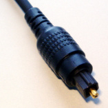
While TOSLINK specifies a few plugs, it is mostly associated with the optical EIAJ/JEITA RC-5720 plug, a.k.a. JIS F05 and CP-1201 - optical, mating with a square-ish shape.
In most contexts, this plug carries S/PDIF protocol (which itself can carry raw PCM, DTS, and AC-3).
Note that the exact same S/PDIF signal can also be carried over copper, then often connected via RCA or BNC, which involves fewer components and is really no more sensitive to EM noise - and avoids any conductor so cannot introduce ground loop issues.
You could argue lasers and fibers are cool, but really it's just a LED (because cheap and short-range), and something more akin to fishing wire (because more robust). That said, it was ahead of its time, and still not really replaced by another well known standard.

Mini-TOSLINK looks like a stereo jack (3.5mm TRS style) but carries the light to its tip.
This allows laptops (and other size-restrained devices) to have one small socket that provides either consumer 3.5mm analog audio, or SPDI/F style digital audio. It was seen e.g. on some portable MiniDisc players, some Apple laptops, and while it still exists it was was never hugely common.
There are physical adapters from TOSLINK to mini-TOSLINK.
See also:
- AES/EBU, a.k.a. AES3
- https://en.wikipedia.org/wiki/TOSLINK
- https://en.wikipedia.org/wiki/TOSLINK#Mini-TOSLINK
Computer
Power supply
AMP/Molex power and Berg power connectors
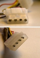
tl;dr: In the context of computers, calling something a Molex connector typically points to this one.
Like other plugs, this is a connector named for a company - Molex is a large company that makes many types of plugs.
Except this one has a more confusing history than that. As far as I can tell right now:
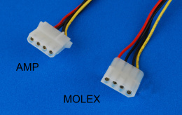
- There was a Molex connector (early 60s?) that resembles (but isn't compatible with) the plug we later knew in PCs (the right one on the image with blue background).
- AMP in 1963 introduced Mate-n-Lok. Its use in PCs picked up later, maybe late seventies(verify).
- ...and became common enough in PCs that 1983, Molex developed Molex 8981 which was fully compatible with AMP Mate-n-Lok. (Well, the 4-position Mate-n-Lok -- Mate-n-Lok is actually a larger family[12] though I'm not sure it was back then(verify)).
- As such, the thing we called Molex around computers for the next couple of decades (seen on larger floppy drives, on PATA HDD and CD/DVD drive connections of the time) in a practical sense is either AMP Mate-n-Lok or Molex 8981 (the difference mainly in sourcing, as they look the same).
- And it was introduced by AMP, so calling it AMP Mate-n-Lok is slightly more accurate in that it doesn't ignore the decade of use that established the connector, calling Molex is much better understood, and practically there is no difference.
- The argument is less relevant now that in most computer uses it has been displaced by SATA power plugs.
- (also, AMP is now called TE, but the connectors are still called AMP for findability)

The Berg plug (apparently named after its designer) was mainly used on 3.5 inch floppy drives.
While sometimes called 4-pin mini-Molex, this one is also an AMP plug, specifically AMP 171822-4 for the cable socket, AMP 171826-4 for the right Angle PCB header.
These plugs are becoming as rare as floppy drives themselves.
See also:
PCIe power, EPS power, etc.
These connectors seem to come from the Molex Mini-Fit family - most resembling a Mini-Fit Jr though actually seems to use a different keying(verify)

The 'PCIe' naming seems to come from the fact that PCIe video card power draw is high enough that it is not sensible to get it through mainboard traces / the PCIe bus, so we decided to get it through a plug like this instead.(verify)
PCIe 6-pin (mostly seen on GPUs)
- officially: two pairs of +12V and Gnd (the last pair is specced as NC)
- unofficially often three pairs of +12V and Gnd (most such cables and PSUs allow real current draw on the third)
PCIe 8-pin - an expansion of the 6-pin (mostly seen on GPUs)
- Three pairs of +12V and Gnd
- with the pin that the 6-pin variant listed as NC now guaranteed to be a +12V
- A plug may separate the 6+2, to be compatible with both 6-pin and 8-pin variants
- the extra 2 add a Gnd and Sense
There seems to now also be a 12-Pin variant for nVidia RTX 3xxx series, apparently for space reasons, because it's barely larger than an 8-pin but can carry more power.

4-pin ATX 12V (mostly seen on motherboards)
- Two pairs of +12V and Gnd
- used for power more directly to the CPU, has been around since roughly the pentium 4
8-pin ATX 12V
- Doesn't exist and, assuming you said it because motherboard, will probably mean you're looking at 8-pin EPS12V (verify)

EPS 12V [13] (mostly seen on server motherboards)
- Mostly seen on server boards (and some higher-power consumer boards), meant for more current to the CPU.
- It is not ATX standard - but is effectively a derivative of it, defined by SSI
- The 8-pin EPS connector is four pairs of +12V and Gnd
- physically incompatible with PCIe 8-pin
- the 4-pin EPS connector is two pairs of +12V and Gnd(verify)
- this plug seems less common than the 8-pin(verify) (probably because 4-pin ATX 12V will do)
4+4 EPS/ATX (on power supplies, plug only)
- Refers to plug only: splittable, so that a PSU needs fewer wires and plastic to accomodate both 4-pin ATX and 8-pin EPS motherboards sockets
- That split cheats a little, but it is hard to plug incorrectly unless you get particularly creative with adapters or hammers.
- In practice, a lot of consumer power supplies just give you both a 4-pin ATX and 8-pin EPS12V, which is less confusing
See also:
- https://en.wikipedia.org/wiki/PCI_Express#Power
- https://en.wikipedia.org/wiki/Power_supply_unit_(computer)#Entry-Level_Power_Supply_Specification
Fan connector

PC fans are often connected with a three-pin connector (polarized variant from the Molex KK family) which supplies 12V, ground, and a sensor wire that the computer can use to count revolutions.
There were a few not-so-standard variation, such as Dell's.
You now commonly see Intel's variation, with a fourth pin to the side.
3-pin:
- 1 - Ground (black)
- 2 - 12V (often red)
- 3 - speed sense (often yellow)
4-pin adds
- 4 - PWM signal - seems to be a voltage signal(verify) so if used at all, it will be used by a transistor in the fan(verify)
6-pin (seen in servers) add:
- 5 - fan presence (lets the computer do a simpler test to see there is one connected)
- 6 - fan fault led (for visual feedback which one is broken, useful in datacenters because of cramped hardware layouts and loud environment)
As the larger sockets are physically an extension on the simper ones, this is often fairly compatible -- as long as you know which one is pin 1, which bits of keying plastic usually help with.
"Can I put a 3-pin fan on a 4-pin socket?"
Yes.
That controller most likely does PWM on that extra pin, meaning 12V is just 12V, so the fan is likely to run at full speed.
You could actually make a 3-pin fan into a 4-pin fan with a little soldering (and a 4-pin connector, transistor, suitable resistor. ...but since 4-pin fans basically cost the same, this is generally not worth doing.
"Can I put a 4-pin fan on a 3-pin socket?"
Usually, because many 4-pin fans are designed to work fine on a 3-pin header.
If they were not, they will probably not function at all - so if it spins up at all, it's probably fine.
Lower speeds, in general
If there is no PWM involved anywhere, you could undervolt a fan with a ghetto-ish fix: splice a fan between the +12V and +5V (e.g. from a molex plug) giving 7V.
However, not all fans reliably spin up at voltages like 7V (even if they will continue to run at 7V if already spinning), so check that it does, always, or you'll sometimes have very little cooling.
This is is also why using an inline potentiometer for speed control is less predictable than PWM.
Using PWM is the preferred method of speed control over lowering voltage e.g. with a potentiometer,
because PWM will typically work down to lower speeds than undervolting (for an combination of reasons that is a little complex and varies per actual fan).
Motherboards officially just put 12V on the power pin. In the 3-pin-fan days some motherboards would PWM the 12V power pin, which works even on 3-pin fans, but has some footnotes - the 4-pin way is a more standard and somewhat more reliable way of doing PWM.
You can buy little speed control boxes that you plug between motherboard and fan.
Which are often but not always PWM based.
Storage
IDE, EIDE, PATA
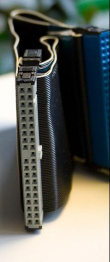
IDE (Integrated Drive Electronics) a hardware bus primarily a ssociated with ATA and its protocol.
IDE can however also refer to some pre-ATA and other not-ATA things.
Once ATA was standard, IDE and ATA were used more or less interchangeably.
Once SATA existed, a distinction between SATA and IDE(-as-in-parallel) became convenient, so both IDE and ATA became a bit vague, and we started using SATA and the retronym PATA (Parallel ATA) became a clearer way to refer to this 40-pin connector.
Notes:
- If there are two devices on a single PATA cable, one is called master and the other the slave (jumpered that way, or sometimes implied via its position on the cable)
- These names are not official. They also do not refer to interaction between the drives at all - both drives operate independently, using their own controllers and both only talking to the host. It was just a way for the host to distinguish between two on the same cable.
- There was also EIDE, Enhanced IDE, referring more vaguely to early adoption of some features of a then-future ATA standards. The term was also abused by marketing at that time
ATAPI
'ATA with Packet Interface Extension' is actually about protocol, not plug - it can be carried over PATA or SATA.
ATAPI is an extension based on SCSI protocol features, that made it more useful for certain (additional) drive types, such as CD, DVD, and tape drives.
In this context, ARMD ('ATAPI Removable Media Device') is practically use mainly used to refer to ATAPI drives other than CD/DVD drives. Often meaning tape drives.
Early CD drives: Panasonic, Sony, and Mitsumi
Before ATAPI caught on as the standard for CD drives (and having multiple ATA controllers was a given on motherboards), these three companies created proprietary interfaces (sometimes called AT-BUS and other things) to connect CD drives of their own styles.
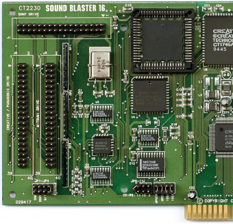
Certain expansion cards, e.g. the Sound Blaster 16, exposed these connectors as a simple way to connect these pre-ATAPI drives without needing to buy a specific separate interface card. (TODO: look up the details)
Sony used a 34-pin IDC/ribbon connector.
Panasonic and Mitsumi used 40-pin IDC/ribbon connectors (that were potentially confusable with PATA connectors, particularly once PATA (speaking ATAPI) later became the standard for CD drives as well).
Side note on ATA
ATA is short for "Advanced Technology Attachment", effectively a set of standards that now encompasses Parallel ATA, ATAPI, Serial ATA (SATA), and more.
ATA versions and introduced features: [14]
- pre-ATA standards had varied limits, particularly in the DOS era
- ATA-1 (1994) - PIO 1 and 2, 28-bit LBA for sizes up to 137GB
- ATA-2 (1996) - PIO 3 and 4, DMA 1 and 2 (the terms 'EIDE' and 'Fast-ATA' appeard around this time)
- ATA-3 (1997) - SMART, connector for 2.5" drives
- ATA-4 (1998) - UDMA 0, 1, 2 ('UDMA 33')
- ATA-5 (2000) - UDMA 3, 4 ('UDMA/66')
- ATA-6 (2002) - UDMA 5 ('UDMA/100'), 48-bit LBA for sizes up to 144 PB
- ATA-7 (2005) - UDMA 6 ('UDMA/133'), SATA 1.0 ('SATA/150')
- ATA-8 (2008?(verify); there is a working draft you can get. Includes SATA 2.x and SATA 3.x?(verify) but those make more sense to get directly, SSD TRIM(verify), and some details)
Since then, almost all development is in SATA, which is its own standard.
SATA has its own versioning: [15]
- SATA 1.0
- SATA 2.0 (2004)
- SATA 2.5 (2005)
- SATA 2.6 (2007)
- SATA 3.0 (2009)
- SATA 3.1 (2011)
- SATA 3.2 (2013)
- SATA 3.3 (2016)
- SATA 3.4 (2018)
- SATA 3.5 (2020)
SATA
-
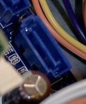
SATA data sockets variant with shroud that makes it a little sturdier and accepts a clip
-
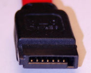
SATA data plug (without clip)
-
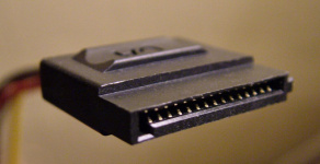
SATA power connector (15-pin)
SATA: Serial ATA, is part of ATA-6 and later. Has basically replaced PATA.
There are variants, but most of us care about the 7-pin data cable (and the 15-pin power cable).
The data socket can be as minimal as just the plastic to hold the contacts, but most sockets are a variation with a plastic shroud (see first image), making it harder to break. This will also accept the clip present on some cables.
Basic SATA's basic power connector has so many pins for scalability reasons - it provides three voltages (3.3V, 5V, 12V), with three pins each to be able to meet requirements of power hungry drives (while not exceepding 1.5A per wire), plus one signalling cable.
This cabling is often not necessary, and there are slimline and micro versions of the power connector, which use simpler wiring, and are good enough for the drives they're meant for.

For external use there is eSATA, which is pin-compatible and functionally identical. The main differences lie in electronic, cable length, and physical specs, and the connector and socket are different enough so that you can't plug SATA cables meant for internal use onto external ports. (There are dumb adapters, but you should be aware of what you're defeating, and will also have trouble around SATA ports that disable themselves at boot if there's no drive on there)

There is also eSATAp (often marked eSATA+), which is a connector that adds power, and the ability to plug in USB into this same socket. Keep in mind that this may be either USB2 or USB3 (you can usually tell by the color).
eSATAp is a variant of eSATA that carries also carries power -- and also USB.
Only SATA's 5V line is guaranteed on this plug, the 12V line is optional.
Desktop computers typically provide 12V, while laptops often don't(verify).
This means eSATAp sockets can typically power 2.5" drives (which only need +5V), but only the desktop variants can power external 3.5" drives (which also need 12V).
eSATApd unofficially refers to having both voltages.
See also:
SAS
SAS and SATA have overlap and in many areas broadly compatible.
This is by design.
You could see
- SAS (Serial Attached SCSI) as the fancier variant of SATA that targets the business market, adding more options and features, more practical variations in controllers, cables with more channels to attach more drives (and have cable failover), options to connect externally as well (e.g. drive bays), and other such options.
- SATA as the simpler, one-drive-at-a-time consumer variant
- that is simpler to use and cheaper to make
- (well, with footnotes. There were things like SATA port multipliers but controller support varied)
The protocol is also very similar, though SATA's required commands are a subset of SAS's(verify)), both are switched, point-to-point, serial, full-duplex, can be assued to be good for approx. 300MByte/sec per port (current typical; both have variations and plans), and can be hot-plugged (electrically, anyway. Your BIOS and OS may have their ideas about enabling and resetting ports).


Pin-compatible with SATA, but the plastic tab in the middle prevents mating SATA as-is
- Drive-wise
The SAS drive interface is SFF-8482.
It looks a lot like SATA, and can indeed connect SATA as well as SAS drives.
The SAS and SATA drive connections are closely related, and in fact pin-compatible. You can physically plug SATA drives onto SAS controllers, the SAS drive connector (SFF-8482) allows it, and SAS can tunnel SATA. This means server backplanes are easily designed to take SAS and SATA alongside each other.
SATA cannot tunnel SAS, and for this reason you cannot use SATA cabling on a SAS drive. Physically because of the extra plastic, but even if you find a physical adapter (they exist, though I'm not 100% on why), it probably won't work(verify).
- Beyond single drives
Because of varied use cases, there are a whole bunch of internal connectors standardized by SAS, e.g. to carry a handful of channels between drive bay backplane and controller.
Many of them are used more in servers, but some of them are obvious choices in handful-of-drives consumer RAID hardware as well.
See e.g. [16]
See also:
mSATA
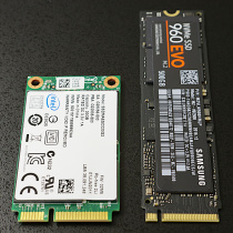
Uses the more general PCI Express Mini Card ('mPCIe') connector as a small drive connector (data+power). ...which caused some confusion, because some sockets were mPCIe, and some mSATA-only (verify) (similar confusion exists around M.2 keyings, actually)
in laptops, mSATA has mostly been displaced by M.2. (due to M.2 NVMe sticks becoming more common, M.2 in desktops is becoming more common, where mSATA rarely appeared)
See also:
M.2
A form factor spec for expansion cards in general, standardized around 2013 (then known as NGFF (Next Generation Form Factor), before it was renamed to M.2)
Can carry include NVMe, SATA 3, USB 3, and (multiple lanes of) PCIe 3.
Consumers mainly see this used for storage, in which case you can consider it a replacement of PCI Express Mini Card connector (and its use for mSATA). Note that M.2 storage can communicate either via SATA or NVMe.
If your PC doesn't have M.2 on-board, there are PCIe plug-in cards with M.2 sockets. If your laptop doesn't, you probably can't use it.
Also keep in mind that it's new enough that not all current systems can boot off M.2 - in which case you can't (easily) use it for your system drive. So you want to check that, because in this aspect there is no upgrade path other than upgrading at least half your computer's hardware.
Widths include 12mm, 16mm, 22mm (typical for storage) and 30 mm.
Lengths include 16, 26, 30, 38, 42, 60, 80 and 110 mm
The size shorthand is those two appended, e.g. 2280 for 22mm by 80mm
There a longer shorthand with more dashes, like WWLL-HH-K-K or WWLL-HH-K, encodes more details (like single/double-sided, maximum thickness of components, and more)
The notchings (specific gaps in the socket/connectors) seem intended to indicate when plugging in a thing almost certainly won't work. If you can plug it in, it should not damage anything, but it is also not guarantee to function.
This also makes notchings loosely correlated with function.
For example:
- B and M are wider use (including PCIe lanes), in practice frequently SSD (speaking SATA and/or NVMe)
- B has one side has short piece with 6 pins
- M has one side has short piece with 5 pins
- BM has both of those notches
- For WiFi you'll see A and E (verify)
There are about a dozen specific notch combinations, but half of them are currently reserved.
For more practical reasons, notchings are also somewhat correlated to sizes, e.g.
- A and E are rarely longer than 30,
- while B and M may use up to the full length, and rarely as short as 30.
See also:
M.2's relation to NVMe
NVMe is storage over PCIe communication.
It is mostly relevant to connecting SSD drives
- but technically, NVMe platter exists (mostly for pluggability in datacenters, not performance)
For storage, NVMe could be considered an
For storage, NVMe could be considered an alternative protocol to SATA
- no but. NVMe can be faster, but for a lot of tasks this is easily overstated
This has led to some misconceptions
- M.2 and NVMe are often seen as roughly the same thing, and used as near-synonyms by some.
- but M.2 is general, NVMe is storage only
- M.2 means storage
- M.2 carries other things - PCIe, USB3, and others
- M.2 storage means NVMe
- but M.2 can carry SATA, or NVMe or both, and which ones a device speaks is up to that device - there is M.2 that speaks just SATA, not NVMe, though not a lot
When M.2 carries NVMe, it
allows higher bandwidth (which even most SSDs don't need yet), and also
has queues that makes it easier to use the parallelism of fancier SSD designs (e.g. allowing parallel reads),
which makes it potentially faster and lower latency than SATA SSD.
How much faster is frequently overstated, at least for most current devices, and most current uses. It's much more a "potentially better", and headroom to be a good interface for a good number of years, much less a guaranteed to be better right now.
More to the point, even if it would for best-case benchmarks, in practice it depends a lot more on the actual workload than the marketing graphs would like you to realize (which is the point of these graphs, of course) because those were made on very specific workloads.
Rather than five times faster everything, you may find increase on most everyday use is more like a few percent to a few dozen percent. Cases that may see a little more may include some servers, some video editing, some games see a modest difference (in loading time, and then only to the degree it is not bound by something else).
So whether the price/performance is worth it depends the same way.
That said, NVMe is at least slightly preferable for SSD, so is likely the preferred interface for SSD in the future(verify).
See also:
Apple's SSD connectors

Apple has used various different connectors over time.
None of them are M.2 - which is half fair because half of them predate M.2.
They include:
- 'first generation', a 6+12 pin (around 2010) (carries mSATA III(verify))
- 'second generation', a 7+17 pin (around 2012) (carries mSATA III(verify))
- 'third generation', a 12+16 pin (around 2014) (carries PCIe (verify))
- with a later variation that uses a 40 pin mezzanine adapter (verify)
- 'fourth generation', (~2015) same connector, but higher speed (verify)
- 'fifth generation', (~2016) same connector, but higher speed and speaks NVMe (verify)
There are often physical adapters from M.2 (the protocols these things speak don't seem to differ),
letting you use more generic SSDs, but you must do the research both on protocol compatibility, and whether it will physically fit.
https://beetstech.com/blog/apple-proprietary-ssd-ultimate-guide-to-specs-and-upgrades
USB

mini-B plug, B plug, A socket, A plug

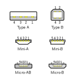
Also shows the micro versions, and the mini-A not in the picture above
-
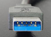
USB3 A plug: the four classical pins, and 5 new ones further in
-
USB3 B plug
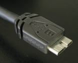
Roughly from most to least common (a guess at that, anyway):
- USB A: The plug/socket seen on the computer side and USB hubs (and sometimes elsewhere, e.g. on printers for direct camera connection)
- USB B: Used on the device side for bulkier devices, such as scanners and printers, where there are no space limitations, and sturdiness is handy
- USB-C: Invertible. Seen on smartphone, some apple products. (released ~2014.
- Developed parallel to USB3, and as of this writing the two don't support all the same features (verify)
- USB micro-B plugs and sockets, meant for use in thinner devices. example: smartphones data/charge cables.
- USB mini-B: Used by not-overly-small devices, such as cameras, MP3 players, some phones. Sockets may be a little sturdier than micro-B in practice.
- USB3 A: Plug adds the extra lines for USB3, but remains the same size. Socket can take earlier (USB1, USB2) USB A.
- USB3 B: Plug adds the extra lines for USB3, and is bigger. Socket can take earlier USB B.(verify)
- USB3 micro-B - basically USB2 alongside USB3(verify), separated with a notch. Seen e.g. on 2.5" external hard drives, USB3 hubs.
- USB3 Micro-A (looks like USB3 micro-B but squarer) exists only as a plug, and seems rare
- USB3 Micro-AB (looks like USB3 micro-B but squarer) refers to a socket that takes USB3 Micro-A and USB3 Micro-B, also seems fairly rare
- USB3 Mini-B - adds pins to the original mini-B. Came much later than the original mini-B and seems to be a cost saver over USB-C that may not be standard?(verify) Seems rare?(verify)
- USB mini-AB socket (socket only), relatively rare, can accept both Mini-A and Mini-B plugs.
- USB micro-AB socket (socket only) that can accept both Micro-A and Micro-B. Defined by USB On The Go (OTG) (2001 standard)
- USB micro-A plugs and sockets, meant for use in thinner devices
- USB mini-A: was never seen that much, perhaps because it is confusable with mini-B.
- There are many non-standard plugs that are relatively rare.
- Say, I've seen cameras use approximately-8-pin sockets with different cables that connect either USB, or things like audio+video. This plug is sometimes confusingly called B(-type).
Notes:
- USB 2 has four pins:
- power lines are 5V and ground
- data is 3.3V differential
- the fifth pin on micro plugs is OTG ID, and is either tied to ground (marking that side as host side) or floating (marking it as device side) (verify)
- USB3 [17]
- leaves all those USB2 in there
- adds five more:
- two differential pairs
- and a ground
- USB version 3 are often indicated with either blue plastic, or SS (for Super Speed, the mode that USB3 adds)
- micro plugs/sockets are often not blue, possibly because it would be hard to see anyway(verify)), and because they're less ambiguous that PC-side A sockets
- The USB1/2 mini connectors are approximately 3mm by 7mm, the micro versions are mostly just thinner, making them useful on very slim devices like smartphones.
See also:
- http://en.wikipedia.org/wiki/Universal_Serial_Bus
- http://en.wikipedia.org/wiki/Universal_Serial_Bus#Mini_and_Micro
- http://en.wikipedia.org/wiki/USB_On-The-Go
8P8C / Ethernet cable
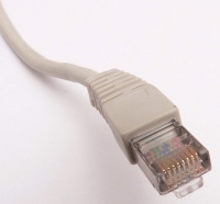
For the series of connectors, see #Modular_connector_.28and_Registered_Jack.29.3B_.3FP.3FC
For the use of 8P8C in ethernet, see 8P8C / RJ45
Firewire (IEEE 1394)
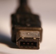

both Firewire-400

which can also be used for S1600 and S3200

IEEE 1394 is better known as FireWire (Apple), and sometimes i.LINK (Sony), and Lynx (Texas Instruments).
It was meant as a successor to parallel SCSI, and is also commonly used for some digital cameras, and for high-end audio and video devices. Was a potential competitor to USB in many areas, but while USB is somewhat slower (depending on which variant of FireWire and USB), USB is more popular for many things.
Connectors include:
- 4-lead
- smaller, e.g. used on more portable devices like cameras. Data-compatible with the 6-lead connector, but doesn't provide power. Initially developed by Sony, later more widely adopted(verify)
- two twisted pairs of data
- 6-lead ('alpha')
- two twisted pairs of data, power
- 9-lead ('beta')
- two twisted pairs of data, power, shield (verify)
- 8P8C connector (used in 1394c)
Standards:
- IEEE 1394, specifically IEEE 1394-1995
- IEEE 1394a, specifically IEEE 1394a-2000, also known as FireWire 400
- Uses the 4-lead and 6-lead ('alpha') connectors
- IEEE 1394b, specifically IEEE 1394b-2002, also known as FireWire 800 (Apple's name)
- adds the 9-lead ('beta') connector
- IEEE 1394c, specifically IEEE 1394c-2006, also known as FireWire S800T
- adds the 8P8C connector
See also:
Thunderbolt
Fast peripheral interconnect by Intel and Apple. (Developed by Intel under the name Light Peak, since renamed)
-
Thunderbolt (1/2) socket
-
USB-C plug. If it's got a bolt near it, or you'd expect it in context, it's thunderbolt 3.
Thunderbolt 1 reuses the Mini DisplayPort connector; thunderbolt capability is indicated by a lightning symbol.
- Can carry DisplayPort, one or more PCI Express lanes, and up to 10W of power.
- Copper cables carry two 10GBbps (1.2GByte/s) lanes, of which any device can use only one (seems a fair-sharing thing)
- Assume ~3 meter max over copper(verify)
- Can daisy-chain a few devices (though individual devices have to have the plugs for it, and allow it)(verify).
Thunderbolt 2
- Much like 1. Largest difference seems to be that a device can use both channels(verify)
Thunderbolt 3 uses USB-C connectors. Plugs and sockets should bear the thunderbolt logo to lessen confusion.
- Speaks more protocols (DisplayPort, PCIe, USB 3, ...)
- Allows adapters to the previous MiniDP plug
- Not guaranteed to carry 10W as before (though USB could choose to do more than that) (verify)
- Assume it can do 20Gbps as before. Short or active cables could do 40Gbps(verify)
On Thunderbolt 3, USB3, and USB-C

USB-C ![]() is a physical connector more than anything else,
in that it is intentionally protocol-agnostic, and there are already a handful of protocols that can be negotiated on top, including
is a physical connector more than anything else,
in that it is intentionally protocol-agnostic, and there are already a handful of protocols that can be negotiated on top, including
- ...or some combination.
It is context-dependent which protocols the endpoints care to speak.
Which is both nice and potentially confusing.
- Yes, it reduces the amount of cables and connectors you need and makes USB more universal.
- But also, there will be various cases of "doesn't work" that will not be easy to explain.
Say, Thunderbolt 3 chose USB-C plugs/cable (previous versions used mini-DisplayPort), so TB3 can in many contexts be seen as an extension of USB3. But a Thunderbolt3 device will do nothing on a USB3-only host. Probably.
USB-C cables are created roughly equally.
...well, that was the plan, anyway. Sure, most combinations will function, but there are footnotes that mostly technicians and gearheads will care for - except when not.
In practice,
- USB-A to USB-C might be USB2 or USB3, depending on the USB-A plug
- (it also can't populate all lanes, because USB2 didn't have thay)
- USB-C-to-USB-C should populate everything
- apparently even these exist in USB2- only variation, but this should be rare
- but yeah, even C-to-C cables exist in half a dozen variants already (see the specs[18])
- USB-C-to-USB-C do not all support the same speed
- USB-C-to-USB-C do not all support faster charging
- and if they pretend to do so, but are out-of-spec knockoff cables, this is somewhat riskier these days, because there is a bunch more current involved than in earlier USB
PS/2
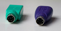
Uses the 6-pin mini-DIN connector. For keyboards, this replaced the larger DIN plug used on AT style computers before PS/2. For mice, this became an alternative to serial port mice, though USB is now also quite common for keyboards and mice.
D-sub (D-subminiature)
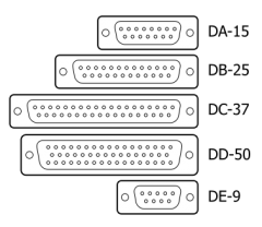

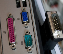
The DA-15M held next to it is a MIDI-on-a-gameport cable
D-subminiature have a keystone-shaped shell for seating and earthing, and typically fastened with screws.
Most have two rows of pins, some three.
Spacing of pins within a row is 2.76mm, rows are 2.84mm apart.
- the 'high density' (HD) variants have 2.3mm pin spacing, 2.0mm row spacing
Coding:
- The second letter indicates the shell size (A through E),
- followed by the number of pins present,
- and sometimes the M or F for male/female (originally P and S for plug and socket)
Given the shell size and pin spacing, there is a typical amount of pins for each size of shell when there are 2 rows: 15 for A, 25 for B, 37 for C, 50 for D, 9 for E.
There are however exceptions, like the three-row variants (e.g. DA-26, DD-50, DE-15), and sometimes other things in there (e.g. DB13W3).
Some common examples:
- DE-9:
- often a serial port (RS232) interface
- DB-25
- Parallel ports
- Serial ports - though they were unnecessarily large, so quickly adapted to replaced with DE-9
- sometimes (older) SCSI (verify)
- DE-15:
- VGA monitor connectors. (Uses three rows of pins. Also technically called HD-15, where HD stands for the High Density of the pins compared to other D-Sub plugs)
- DA-15:
- game port (mostly seen on older PC sound cards), originally for joysticks, later also used for MIDI
- in earlier networking, the AUI connector was the way to connect distinct physical layers to a unified interface (analogous to the later MII), that with adapters could go to 10Base2, 10Base5, 10BaseT, and more
Some people abuse specific letter codes thinking that anything just refers to the D-sub plugs in general, and started patterns of misleading use for those that do know what they mean, e.g. DB15 to refer to DE15 (VGA) or DA15 (gameport).
There are smaller variants called Micro-D and Nano-D, mostly seen in military and space use.
- http://en.wikipedia.org/wiki/D-subminiature
- http://en.wikipedia.org/wiki/VGA_connector
- http://en.wikipedia.org/wiki/DB13W3 ('Sun video', or SGI/DCC)
Micro D-sub
Smaller and denser variants of the D-shell and pins idea.
(also called mini, but this is arguably extra confusing, in that (regular) D-sub is short for 'D-subminiature')
Smaller pitches (at least 1.27mm/.050"),
and may have pins aligned grid-like rather than in a triangle,
though there are probably various distinct series that fit this vague description.
I'm not sure what series these are officially part of - sites now tend to categorize them under SCSI connectors, or computing miscellany.
Ones I've come across:

- Micro D50
- 1.27mm (.050") pitch
- aligned between rows

- Micro D68, which you may recognize as 'something to do with SCSI'
- 1.27mm (.050") pitch
- aligned between rows
- Micro D25
- 1.27mm (.050") pitch
- triangle alignment between rows(verify)
Adapters exist to e.g. Micro ribbon for SCSI
Ribbon-cable-and-IDC
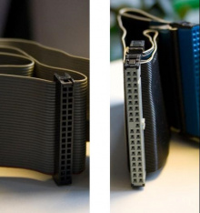
(The ribbon cable is just the lots-of-wires-side-by-side part, which itself does not imply a connector but IDC is fairly common; smaller variants are now often flat flex)
The plug is called an insulation-displacement connector, IDC (see also DIN 41651)
The name name that refers to the fact that you can press these connectors onto ribbon cables - the connectors have blades that cut through the insulation. In some contexts known as just ribbon cables, not naming the plug. E.g. in computer building, one basically implies the other
The pin headers can be very basic, so this is a cheap yet solid thing to connect something low-pin-count, low speed, that doesn't need to be changed very often.
The IDC pitch (hole spacing) is often 2.54mm (0.1 inch), though there are variations - for example, parallel ATA connectors for laptop disks often had 2.0mm pitch.
IDC were once common in computers, now largely replaced.
Some that remain:
- Some motherboard-connected ports not directly on motherboard, e.g.
- an extra serial port, audio connectors (varying pin details)
- extra USB ports (varying pin details), and more
- used internally in a lot of places
- but may be entirely specific to a case, and less standard than various of the above.
Once common, no longer:
- 40-pin (2x20, 2.54mm pitch - 3.5" hard drive connectors (parallel ATA),
- Mostly a 40 pin IDC connector wired straight through, but with pin 20 blocked
- 80-conductor cables still only use the same pins, but put a grounded wire between each to reduce crosstalk
- (note that such details make IDE cables not the best choice to reuse as non-IDE interconnecting)
- 34-pin (2x17), 2.54mm pitch - floppy connectors (controller side, and drive side for 3.5" floppy drives)
- also old Sony CDROM drives, see above
- 44-pin (2x22), 2.0mm pitch - 2.5" notebook hard drive connectors (parallel ATA)
See also:
- http://en.wikipedia.org/wiki/Insulation-displacement_connector
- http://en.wikipedia.org/wiki/Parallel_ATA
Micro ribbon connector
Micro ribbon connector or miniature ribbon connector and some other names
The shell's shape is much like that in D-sub, but the connectors are strips instead of pins, and fastening can be clips or screws (though there can be a strong correlation with any one connector. Also, I have seen sockets accepting both).
I think I've found pin counts like 14, 20, 26, 36, 50, and 68(verify), but it seems there are a few specific selections for specific uses. Most are now rarely seen anyway.
There are actually two sizes of this connector,
- the larger, more common one with a 2.16mm / 0.085" pitch
- the smaller with a 1.27 mm / 0.050" pitch - and this smaller variant doesn't seem to have a very official separate name. I've seen it referred to as mini-Centronics, miniature delta ribbon (MDR), mini D ribbon.
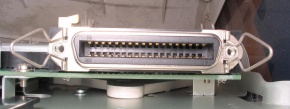

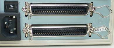
The 'micro ribbon connector' name now seems somewhat odd
- it's not micro, it's not even small
- the larger one is/was more common and basically called micro, and then there's a mini version.
- So mini(-micro) is smaller than micro, great
- ribbon is easily understood as ribbon cable e.g. seen on IDC connectors, or perhaps flat flex cable, neither of which are commonly used on this connector (does ribbon actually refer to the style of contact?(verify))
Example uses:
- IEEE 1284 is parallel port style communication
- defines use of
- the 36-pin larger variant (sometimes MDR36, sometimes HPCN36 'HPCentronics'). This use is known as the Centronics connector because that company basically introduced the use for printers, typically with DB-25 on the other side. Use in printers was displaced by USB.
- (people will easily call other micro ribbon connectors Centronics because of this association).
- the 36-pin mini variant (which was never used much here but which you'ld probably call mini-Centronics)
- (and also 25-pin D-sub)
- the 36-pin larger variant (sometimes MDR36, sometimes HPCN36 'HPCentronics'). This use is known as the Centronics connector because that company basically introduced the use for printers, typically with DB-25 on the other side. Use in printers was displaced by USB.
- See e.g. https://en.wikipedia.org/wiki/File:Mini-Centronics_36_pin_with_Micro-Centronics_36_pin.jpg
- SCSI
- I have yet to do a deep dive into the history of SCSI connectors, please do your own.
- but it seems to use at least the 50-pin connector in earlier days
- there were some vendors that used the mini-Centronics connector
- (SCSI it also used IDC headers, and what looks like a micro D-Sub, 50 and 68-pin variants, and some others)


- Camera Link cables use the 26-pin mini variant
- standardish, but used mostly in somewhat older professional kit, so hard to get in shops
- TODO: verify whether Japan's D-Terminal is using mini-MDR14
See also:
- https://en.wikipedia.org/wiki/Micro_ribbon_connector
- https://en.wikipedia.org/wiki/IEEE_1284#IEEE_1284_connectors_and_cables
Internal bus
Mobile devices
Phone (landline)
Modular connector (?P?C); Registered Jack
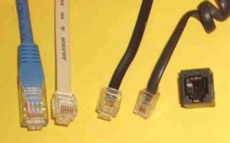
Modular connector (when it refers to a specific connector) were developed for phone uses, though have also found uses as e.g. board-to-board connectors when space is not cramped.
Variations of socket and plug are named by
- how many positions there could fill (which also implies the plug/socket width), and
- how many conductors are actually present (typically filled out from the center positions)
For example, 6P2C has 6 positions and two conductors, 8P8C has 8 positions and has conductors in all positions.
The 2, 4, 6, 8 positions/lead connectors are mostly standard, 10P10C and further variations also exist.
See also:
- http://en.wikipedia.org/wiki/Modular_connector (plugs)
- http://en.wikipedia.org/wiki/4P4C
- http://en.wikipedia.org/wiki/10P10C
RJ meaning analog phone
Registered Jack refers to a handful of analog telephone pinouts / wiring standards, most of them on these modular connectors (RJ that uses other plugs includes the RJ21 centronics style connector, and some adapters).
Once you get into the details and specific plugs, there is only loose association between specific connectors and likely uses.
This can be useful to know because you often have more luck finding these plugs and sockets by the associated RJ uses.
Consider for example
- 4P4C ~ RJ22 - mostly used to connect handsets to phones (two pairs, one for the microphone and one for the speaker)
- also RJ9, RJ10 but people seem to mix these quite vaguely so you can consider RJ9, RJ10, RJ22 as synonyms until you're doing the wiring
- 4P2C exists, but is not used much
- 6P2C ~ RJ11 (one-pair, one telephone line)
- (You also see 6P4C sold as RJ11 though this is technically incorrect)
- 6P4C ~ RJ14 (two-pair, two telephone lines)
- 6P6C ~ RJ25 and RJ12 (three-pair, three telephone lines)
- 8P8C ~ RJ45, RJ48 (ethernet, multi-line telephone, ISDN, T1 / DDS)
The ones familiar to consumers are mostly 4P on phone handsets, 6P for analog phone lines, and 8P for networking.
Notes:
- There are often two plugs for the same use, which seems to be because of the type of wiring, e.g. the stabs on the pins mean RJ12 is for solid, RJ25 is for stranded(verify).
- This is about wire crimping and such, and using the wrong type will typically work, but issues arise sooner rather than later, so in professional setups this is not a detail
See also:
- http://en.wikipedia.org/wiki/Registered_jack (telephone wiring)
RJ45 meaning ethernet?
Well, no. But that technicality was lost long ago.
When a few variants of wiring Ethernet (e.g. 10Base-T, 100BaseTX) started using the 8P8C plug (this wiring), and became popular, RJ45 shifted to mean "Computers using Ethernet" (and made us abandon and forget things like 10BASE2 and 10BASE5).
...even though
- the 8P8C plug is used by other standards as well (and by non-standards)
- RJ45 is a phone-wiring pinout
- Ethernet is a large set of standards with a multitude of connectors
The association with Ethernet is now strong enough that searching for RJ45 pinout shows you the TIA/EIA-568-B pinout instead,
and even some proprietary pinouts, before you get anything mentioning a phone.
It's actually hard to do a web search for the original phone wiring, and you'll even get hits titled "Could RJ45 be used for telephone?"
To add to the confusion, 8P8C was for a time seen connecting networking and phones -- because a single analog phone line (middle pins) and 100MBit ethernet (which avoided the middle pins) could coexist on the same plug, which some offices used to reduce the amount of wiring and sockets to install. (Today, the same offices would use VOIP phones and only care about networking)
See also:
Less standard ?P?C uses
Many. It's a fairly convenient connector that clicks in and won't fall out, cheap, and the wires are easy enough to get.
Landline wallplug
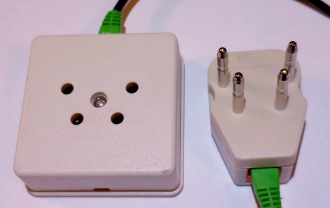
A lot of countries have switched to RJ11 within the house (and sometimes RJ45), often away from something more local.
Countries that still haven't fully shed themselves of older plugs (often just in older houses) include...
- Britain - BS 6312 [21]
- Germany - TAE [22]
- Loosely resembles F-010 (flat things on the side)
- Austria - TDO [23]
- Loosely resembles TAE
- France - F-010 [24]
- Loosely resembles TAE (flat things on the side)
- Australia - 600-series [25]
- Netherlands - seems to just be known as phone plug, not sure whether it has a known name
- Brazil - Telebrás (named for a company)
- North America - Bell Systems 404A and 505A (60s), changed to RJ since the 70s
- South Africa - Protea (70s to 90s)
- Poland - WT-4, GTN-4 (verify)
- Sweden, iceland - SS 455 15 50[26]
- Italy [27]
Also, some countries had a distinct plug used only for ISDN (which now barely exists) or ADSL (now often also RJ)
Memory cards
See also
SD and MMC

(not showing extra UHS pins)
Physical size: There's mainly
- SD (24x32x2.1mm) (MMC was apparerently a little thinner?)
- microSD (11x15x1.0mm)
- previously called TransFlash (abbreviated TF and T-Flash), and some parts of the world still prefer that name
- (There's also MiniSD, which never really took off)
The variants are pin-compatible (some footnotes on the faster ones with extra pins), so adapters to larger sizes exist, and the choice of which you want relates more to the device. For example, cameras and laptops and generic card readers often prefer SD, which is a little sturdier and less fiddly to move around, smartphones use microSD because of the smaller size and it being more or less permanently in there anyway.
Storage size:
When released around 2000
- allowed apparently allowed for up to 2GB(verify) though were typically tens of megabytes large
SDHC (~2007)
- allowed sizes up to 32GB
SDXC (2009 and later)
- allow sizes up to 2TB,
- and optionally allowed designs that go at higher speeds.
Speed:
Basic speed is 12MB/s, or 25MB/s when clocked at double rate
UHS variants
- go up to 100MB/s or a few multiples of that depending on the UHS variant
- and require card and reader support go at these speeds (or will go to the basic speed).
Notes that readers that were connected via USB2 will often be go no faster than 30MByte/s anyway.
See also:
- More technical details at: On_computer_memory#Secure_Digital_.28SD.2C_miniSD.2C_microSD.29.2C_and_MMC_details
On MMC
In today's context, MultiMediaCard (MMC) (since roughly 1997) was the predecessor for SD cards (since 1999).
SD has been more common than physical MMC card for a long while now but variants of MMC (some of them specialized or local) have come out until recently, and there is less difference than 'predecessor' might suggest.
Also, because SD builds on MMC both physically and in terms of protocol, many SD controllers will still accept MMC cards.
Like SD, MMC had some size variants (see e.g. MMCplus, MMCmicro).
- There is more MMC-based variation, in part because it was an open standard so let companies roll their own.
Worth mentioning is eMMC, basically a flash chip meant for internal use, that happens to be built on MMC.
It was in common use for internal storage in phones and tables until it was displaced by UFS.
See also:
CompactFlash (CF)
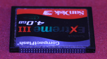
Basically a PATA bus, and talking ATA, directly on the side of a memory card.
Often contained flash (which was initially fairly small), though initially also for very small hard drives (microdrives).
It offered good features early on (compared e.g. to SmartMedia), but was later displaced by smaller and faster formats - though the sturdiness let it hold on in certain uses, e.g. photography where huge storage size is less important.
Physical size: 36m high, 43mm wide
- Type I is 3.3mm thick
- type II is 5mm thick
Type II was mostly used by microdrives, also because II is allowed to draw more current than I. As microdrives were fairly quickly displaced by flash-based storage, most CF cards are Type I, and not all devices do not fit Type II cards(verify).
There are derivations, like CFast (SATA bus) and CFexpress (PCIe bus) but these are essentially different formats.
Initially, storage size was dozens to hundreds of MByts, because when it was designed (mid-nineties) a GByte was more storage than a lot of PCs had. In the 2000s they grew to dozens of GBytes. (Recent CF5.0 allows much larger, though in a lot of uses a hundred GByte or so is more than you need, and larger may be better served by a more modern, faster format)
Because it's really just ATA, maximum transfer speed varies with ATA version. Original specs used PIO modes, at 25MB/s,
later UDMA modes supported up to 166MB/s.
- (and some CF even actually is that fast, which is still on par with modern SD cards).
- yet most regular cards didn't go above 20MB/s or 30MByte/s, and maybe single digits from cheap ones (note: also like cheap SD today).
- The x speed rating is multiples of 150KB/s (like in CDs), so e.g.
- 133x is approx 20 MB/s
- 1066x is approx 160MB/s.
- Note that the listed speed is usually the read speed, not the write speed.
See also:
Memory Stick (Duo, Pro, Micro (M2), etc.)
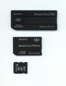
The three sizes are electronically largely identical, and adapters from M2 to Duo-size and standard-size exist.
Seen on mobile phones, cameras, The PlayStation Portable, etc. Competed mainly with SD and CF at the time.
Maximum space:
- original: 128MB
- PRO: 32GB (probably the most common)
- XC: 2TB
There are three physical sizes (which you could call Standard, Duo, and Micro):
- that of the Memory Stick Standard, PRO (longer and thicker than the Duo)
- that of the Memory Stick Duo, PRO Duo, PRO-HG Duo (shorter and thinner than the standard)
- that of the Memory Stick Micro (M2)
If you haven't seen them before
- the Standard and Duo's angled corners make them somewhat confusable with SD.
- The size of the micro (M2) makes it somewhat confusable with the microSD.
See also:
xD
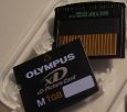
A few types, sizes up to 512MB and 2GB varying with them.
Apparently quite similar to SmartMedia
https://commons.wikimedia.org/w/index.php?search=xD+card&title=Special:MediaSearch&go=Go&type=image
SmartMedia (SM)
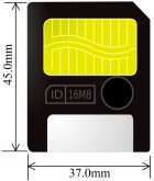
- quite thin (0.76mm), feels fragile for its other dimensions
- capacity limited to 128MB (...so not seen much anymore)
See also:
RF/coax connectors
Plugs desiged (mostly in terms of shielding and impedance) to carry radio frequencies, associated with carrying video, data, and more.
http://en.wikipedia.org/wiki/RF_connector
Belling-Lee (IEC 169-2)
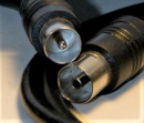
Used for in-your-house TV and radio connectors in some European countries, and Australia.
Diameter is around 9.5mm.
Some people seem to call this a PAL connector, which is apparently mostly an association with the countries this is mostly seen in.
Some call it a coax plug, which is even vaguer.
Note that on houses with more serious installations, it's not unusual to see these only in the eventual wall-plug and the cable that goes to the TV, while everything up to that point might se F connectors or such - in part because the Belling-Lee plugs are not ideal for VHF and UHF frequencies (but fine for MW and Shortwave) and there are some losses every time you connect them(verify) so you really don't want them more than once in your chain if you can help it.
See also:
F Connector (IEC 169-24)

Diameter: ~14.5mm
Often used for cable television / cable modems, satellite television, and (American) TV aerial connections.
A little less lossy for VHF and UHF than Belling-Lee is, so is seen in more places in infrastructure(verify).
See also:
- http://en.wikipedia.org/wiki/F_connector
- Confusables: TODO
BNC
-
BNC connector (socket/inner) on an old network card (the plastic thread is meant for a fastening ring and is not part of BNC(verify))
-
BNC connector (outer)
BNC, Bayonet Neill-Concelman (apparently also sometimes Baby Neill-Concelman connector, Baby N connector, British naval connector(verify), bayonet nut connector) was once common for networking (e.g. 10BASE2, others).
Still used for some antennae, video (then often composite video), oscilloscopes, occasionally audio and other things, for the ability to carry higher bandwidth analog signals, the shielding, or both.
The plug is designed for a particular characteristic impedance, often 50 or 75 Ohm,
and while there are two different plugs, they have only slightly different dimensions and doesn't require a lot of force to mate them,
and while they often look different there is no simple definitive way to tell which is which.
This makes little difference under order of 10MHz, but high bandwidth applications will care about mismatches.
The dimensions vary a little between these two, but order of magnitude, the barrel is roughly 10mm and the plug's outer dimensions roughly 15mm
See also:
TNC

TNC, Threaded Neill-Concelman, is a variation on BNC with a screw thread system (BNC uses bayonet).
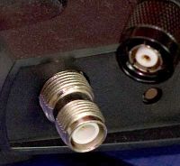
Reverse TNC is reverse in that the inward/outward threading is switched between male and female plugs. This is seen e.g. in older/larger WiFi antennas, an area where the smaller R-SMA is also regularly seen for the smaller ones(verify).
See also:
- http://en.wikipedia.org/wiki/TNC_connector
- http://en.wikipedia.org/wiki/TNC_connector#Reverse-polarity_TNC
C connector
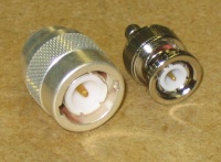
The Type C Connector looks like BNC, but is bigger.
(BNC was developed as a smaller version of this [28])
See also:
Some smaller RF connectors
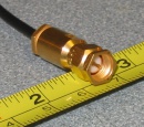

SMA is short for for SubMiniature version A (There are also SMB and SMC connectors)
Rated to 12 GHz or sometimes more.
Diameter: ~6mm for the thread/female, ~8mm for the male/outside
-
RP-SMA / RSMA (male) (on a PCI WiFi card)
-
RP-SMA / RSMA (female) (on an antenna for that same card)
A variation called RP-SMA ('reverse polarity') is seen used in WiFi antenna connectors (the larger R-TNC also sees use there, mostly on older APs).

SMB is similar in purpose to SMA (though only rated up to 4 GHz), but
- smaller (~4mm for the thread/female)
- snap-on rather than threaded.
SSMB is a smaller variant (2.7mm?(verify))

MCX is similar to SMB (also snap-on rather than threaded, rated to 6 GHz), but smaller (3.05mm?)
MMCX is an even smaller variant (2.5mm)
See also:
- http://en.wikipedia.org/wiki/MCX_connector
- https://www.everythingrf.com/community/what-are-mcx-connectors
U.FL / MHF / I-PEX / IPAX / IPX / AMC / UMCC
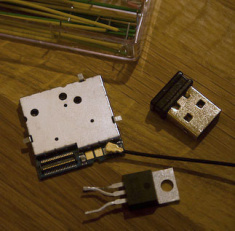

These various names all refer to tiny (2.0mm) connectors for high-frequency RF signals (up to approx 6GHz), and seem mostly interchangeable(verify).
Seen in various mobile and wireless applications.
There are adapters to things like (RP-)SMA sold for applications such as WiFi, mobile modules (particularly machine-to-machine hardware), and others.
See also:
Unsorted RF connectors
CRC-9 (3mm)
TS-9 (3mm)
MC-Card (2mm)
Power - device side
Low/medium voltage, device side
...e.g. adapters, battery packs, solar panels, and such.
Meaning up to a dozen volts, generally up to an amp or two.
DC connectors, EIAJ power, coaxial and more

A lot more plugs get used for this - because particularly under 20V there are few requirements,
so a lot of plugs are fine to use in physical terms.
Perhaps the most recognizable is the concentric barrel-style (some of them within the EIAJ set, some not), which is probably also the subset least likely to be used for other things.
Most are not so much standardized as they are used by convention.
Low-voltage power, usually DC.
The image on the right is a selection of connectors from one of those "20 in one DC adapter kit".
From top to bottom:
- 2.5mm TS
- 3.5mm TS (confusable with audio)
- 5.0mm barrel (~6.2mm tip) (verify)
- EIAJ-01 (2.35mm barrel, 0.7mm inner diameter)
- 3.5mm barrel (1.35mm(verify) inner diameter)
- EIAJ-02 (4.0mm barrel, 1.7mm inner diameter)
- 5.5mm barrel, for 1.5mm pin
- 5.5mm barrel, for 2.5mm pin

Terms, standards, plugs:
- IEC 60130-10 (:1971) defines five/seven connectors
- Type A: 5.5 mm outer diameter, 2.1 mm inner diameter (seems the most common?)
- Type A: 5.5 mm outer diameter, 2.5 mm inner diameter
- Type B: 6.0 mm outer diameter, 2.1 mm inner diameter
- Type B: 6.0 mm outer diameter, 2.5 mm inner diameter
- Type C: 3.8 mm outer diameter, 1.4 mm inner diameter
- Type D: 6.3 mm outer diameter, 3.1 mm inner diameter
- Type E: 3.4 mm outer diameter, 1.3 mm inner diameter
- 'EIAJ connector' usually refers to one of the EIAJ RC-5320A connectors, rather than the other two:
- EIAJ RC-5320A [29] defines five different thicknesses of barrel pairs rated for 2A. Yellow-tipped DC connectors are likely to be one of these.
- note that this is simplified -- these have inner and outer diameter for both plug and socket
- EIAJ RC5322
- Barrel type connectors, 6mm outer, 3.1mm inner radius. Pin is 1.0mm
- wide (6.5mm) plastic tip, apparently to avoid contact in cars and such
- EIAJ RC-5322
- EIAJ RC5321
- TRS-like connectors, different radii
- EIAJ RC-5321
Telling which one you have or need is sometimes be a bit of a challenge.
Small mismatches on the slightly-smaller side tend to be okay, because these are often held by spring contacts.
Barrel sockets often don't have a solid inside but two (spring?) contacts.
- So e.g. a socket made for 5.5mm outer, 2.1mm inner diameter
- will likely also accept 4mm 2.1mm,
- and probably 5.5mm 2.5mm.
- though a 5.5mm outer, 3.4mm inner may not make contact.
However, a socket with a 2.5mm pin won't accept a 2.1mm inner-diameter.
The polarity for DC barrel type is typically tip-positive, i.e. the pin-inside is positive, the outide is negative.
The main notable exception is audio effect pedals.
See also:
- http://en.wikipedia.org/wiki/DC_connector
- http://en.wikipedia.org/wiki/Coaxial_power_connector
- http://en.wikipedia.org/wiki/EIAJ_connector
- http://en.wikipedia.org/wiki/Coaxial_power_connector#DIN_45323_power_connectors
- http://www.accesscomms.com.au/reference/outputplugscb.htm
3-Pin and 4-Pin DC Plugs
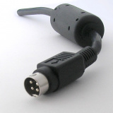
When you see pins thick enough to do more than signal, you are often looking at DC power plugs.
There seem to be a bunch of these, most probably unrelated in origin, probably unified mostly in "seems solid, had has the two/three/four thick-enough pins I need", some of which seem to be niche de facto standards.
Many don't seem to have any singular standard, name, or pinout, though I've seen various with specific keying shapes that do make them a very specific plug.
I've not made a selection of these to show here - you're on your own for now.
Everyday names seem to include:
- snap and lock (though not all variants lock),
- (incorrectly(verify)) power mini-DIN, power DIN - misleading as this does not mate with any mini-DIN plugs or sockets, because of the thicker pins than DIN, and often larger shell (the ones I saw were ~10mm instead of mini-DIN's 9.5mm)
Often used to deliver two different voltages, possibly at a little more current than basic DC plugs are comfortable with.
Seen in cars or RC
Cigarette lighter plug
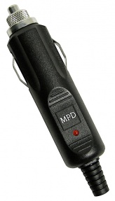
Known as cigar(ette) lighter plug, vehicle receptible, and others. Also called a 12V plug, since this is usually what is provided (some exceptions).
Note that there are actually three variations of this plug, with mildly different sizes.
Since many have plugs with multiple millimeters of spring on the side, they tend to be more or less interchangeable, though some combinations may be too loose, or too tight.
See also:
Vehicle chargers
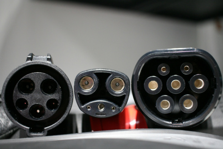
Not depicted: either CCS plug
Interestingly, those boxes on the wall that we call chargers (and are actually called 'electric vehicle supply equipment', EVSE) are typically little more than
- some safety interlocks - they don't switch on power until they're pretty sure there's a car on the other side
- communicate how much power this box can safely pass through - because most cars can draw more than smaller EVSEs and/or home circuits can deliver
...and almost nothing more. It's the car that does the actual charge management, decides how much to draw, does any any necessary rectification of AC, and voltage conversion.
...that is, as long as we're talking about the AC chargers - which is all that Type 1 and Type 2 can do.
AC charging was meant to be simple and convenient, because it amounts to just plugging it into the wall -- if often on a separate circuit.
IEC Type 1, SAE J1772
IEC 62196 Type 1, a.k.a. SAE J1772, J plug, Yazaki
https://en.wikipedia.org/wiki/SAE_J1772
IEC Type 2, a.k.a. Mennekes
IEC 62196 Type 2, a.k.a. Type 2, Mennekes
Used e.g. in Europe, can carry 1-phase AC, 3-phase AC, or DC.
(And this makes little sense in the US because 3-phase power is rare in domestic settings. You see the plug, but it will )
https://en.wikipedia.org/wiki/Type_2_connector
IEC Type 3, a.k.a. Scame
Refers to two distinct variants.
Briefly used, mostly in France and Italy, but replaced by Type 2 (and Type 1)
Combined Charging System (CCS)
For context: Type 1 and type 2 as mentioned above are AC charging, which means that charger on your wall can be nothing more than just feeding through your regular wallplug power with little more than a few contactors for safety (the actual conversion is done in the car).
DC charging involves more complexity and a more expensive box on your wall -- but can be faster, so we added that later.
Since Type 1 and Type 2 plugs already existed, we just added separate DC lines, to both, for easier backward compatibility.
"CCS Combo 1" a.k.a. CCS1
- adds DC to Type 1
- US, mostly
"CCS Combo 2" a.k.a Combo 2, CCS2,
- adds DC to Type 2
- Europe - the EU has basically mandated CCS combo 2.
Notes:
- each area uses 'CCS' to refer to their variant of it.
- Because the plug (Type 1, Type 2) relates to how the power grid is set up (the EU has three-phase power in most places, the US rarely does that on residences), that is the part that means CCS1 and CCS2 are as incompatible as the Type 1 and Type 2 they are based off..
Tesla
Tesla has a plug that used to be very proprietary.
It allows both AC charging and DC charging, and over the same pins, so can be a smaller plug, at the cost of the car and charger being a little more complex and expensive.
This is in part Tesla doing their own thing -- but to be fair, but the plug was planned when the others (particulary CCS) barely existed, so it makes sense.
NACS
The EU had mandated a universal thing (Type2, or Type2 Combo2 (verify)), so everything sold in the EU used that (incuding Tesla), so Tesla's proprietary plug was mostly just used in the US.
Then the US noticed that without standardization, they had more of a mess of variations of both plugs, and the capability of things behind that wire, and called for a #North American Charging Standard.
The outcome is that manufacturers now all seem to be committing to the Tesla plug.
That Tesla plug and protocol was previously proprietary (which was why their charging stations were unusable by anyone else),
but opened up the standard for the occasion.
The plug is physically the same as it was on Teslas, but it does more things now,
and moved to become more compatible with CCS,
so in theory things will become more compatible, though in practice there are some exception cases.
(Remember how universal-but-not-really-and-it's-hard-to-explain-why USB charging is? (and how USB-C managed to make that better but not actually solve it?) Ideally that won't still happen here.)
See also:
https://en.wikipedia.org/wiki/North_American_Charging_Standard
CHAdeMO
DC charging, Japan
https://en.wikipedia.org/wiki/CHAdeMO
GB/T
GB/T 20234.3
DC charging, China
https://en.wikipedia.org/wiki/GB/T_charging_standard
ChaoJi
Proposed DC-only standard to replace CHAdeMO and GB/T
https://en.wikipedia.org/wiki/ChaoJi
Avcon
https://en.wikipedia.org/wiki/Avcon
More specific, less standard (car, low voltage/data)
OBD-II
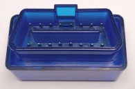
On-Board Diagnostics is only required is to transmit emission-related data(verify), but typically also exposes a bunch of other information useful for mechanics to give clues to problems - mostly live values from the engine, and logged errors[30].
There were a few mostly-proprietary things that had implemented this idea.
OBD-II was the first wider standardization of the idea.
In the plug, aside aside from power (12 or 24V battery, and chassis ground)
It can carry three different standard things:
- CAN (ISO 15765-4, SAE J2284)
- a 41.6Kbps PWM (on two wires, plus ground) or
- a 10.4Kbps Variable Pulse Width (on one wire, plus ground)
...plus seven pins of "whatever the manufacturer thinks up"
https://en.wikipedia.org/wiki/On-board_diagnostics#OBD-II_diagnostic_connector
SAE connector
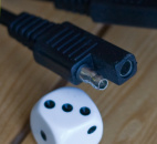
DC power.
Mates with an identical plug. Seen in motorcycles, cars, batteries for such, some solar panels, and such.
Meant to be wired so that the exposed lead from the power source may safely touch the car chassis.
See also:
- http://en.wikipedia.org/wiki/DC_connector#SAE_Connector
- http://images.google.com/images?q=%22SAE%20connector%22
Mostly seen in RC applications
Deans ultra
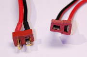
The Deans Ultra is a polarized connector made to carry serious current for its size (smaller than e.g. Tamiya), largely because of the connector shape.
I've seen connectors called "T plug" that seem to be knockoffs.
Flat contacts, one side with springs that push the other side for good contact area.
Rated up to 60A. (but there are some cheap imitations that you don't want to push that high - I recall some rated at 10A(verify))
There is also a smaller micro Deans, rated for a dozen amps.
Powerpole
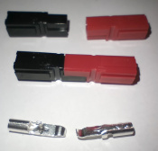
You shouldn't be able to touch those contacts once in the shrouds.
Mixing colors to show how they mate, you should probably not do that in practice.
The plug mates with another copy of itself, and shields its contacts from direct touch, and e.g. touching a car chassis.
Powerpoles are somewhat larger than other choices - but unless you don't have the space, that can be a feature in that it makes it mechanically easier to pull apart (than some other high-amp choices), and may last somewhat longer.
Due to the shape of the contacts they should never fall apart, but if you're worried (e.g. in moving mechanisms) there are retention clips.
Anderson Powerpole (also known as sermos(verify)) refers to a family of connectors, apparently mostly:
- PP10-30
- PP15/45
- PP75
- PP120
- PP180
Note that Anderson is a wider company with many other products, some of which even look like powerpoles, like Anderson SB50, which also seem to use the same contacts as PP75 (verify), but have casings with specific keyings.
Spec-wise
When people say 'powerpole' they often mean PP15/45 - which are three(verify) variants that share the same housing.
The number relates to amperage spec, which has slightly different contacts good for 15A, 30A, or 45A(verify), (though the specs suggest options in which it can be higher and lower than what the model number suggests) and takes different thicknesses of wire more easily.
Combinations
The plastic can also slot into the next side by side, horizontally and/or vertically.
There seem to be variants that amount to two of these already bonded side by side (either direction)
There are also shells without plugs, that let you collect individual and/or bonded variants(verify) into a larger sort of plug.
See also:
Tamiya
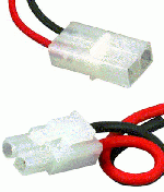
Tamiya is regularly seen in RC battery packs. Seems to refer to the plastic's plug/hole shapes (resembles a 2-pin Molex Mini-Fit Jr.) that make this a polarized connection (the square one is positive, the rounded-on-one-side one is ground).
Tamiya seems to be considered a cheapish choice that is good enough for up to a few amps. Or more, depending on the shape and material of the actual connectors(verify).
Also exists in mini variation.
EC3
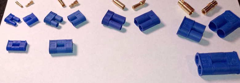
EC3 is a polarized plastic plug around banana-style connectors, and rated to approx 60A. They're relatively cheap(verify), so are handy all-round plugs.
People report them being a little easier to separate than Deans. The plastic may deform when things do heat up, though.
Of the variants, EC3 seems most common, but there seem to be at least a EC5, a small EC2, and a chunky EC8 as well.
XT60
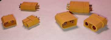
XT60 is a polarized bullet-based plug rated for ~60A, and uses plastic that deals with temperature better (...though 60A is a bunch).
There are more variants of this, like XT30 and XT90
See also
Mains power, device side
IEC connectors
Refers to IEC 60320 (IEC 320 before the renumbering), the plug/socket system commonly used on devices which can use various socket-to-device wires.
The male and female versions of a type connector have different numbers.
C1 through C24 are defined.
For a few there are variations (e.g. C7/C8), and some are variants of other IEC plugs (e.g. C17/C18 is unearthed variant of C13/C14).
The most common are probably:

(pairs with C13)
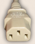
(pairs with C14)
- C13/C14, commonly associated with PC power supplies, and other devices that may need its moderate current rating (over e.g. C5/C6), including some professional audio equipment.
- Rated at 10A
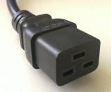
- C19/C20
- Rated at 16A
- seen where you may need a bit more current than C13/C14 gives
- e.g. computer racks may have C19-to-C14 or C19-to-C20 Power Distribution Units

(pairs with C5)
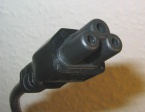
(pairs with C6)
- C5/C6, regularly seen in laptop power supplies and other PC-related power supplies (smaller than C19/20, still grounded)
- rated for 2.5A

(pairs with C7)

(pairs with C8)
- C7/C8 (a.k.a. 'figure eight', 'shotgun'), unpolarized, ungrounded, is seen on various lower-power devices, from radios to VCRs, some laptop power supplies, game consoles.
- rated at 2.5A
- polarized C7 won't fit into unpolarized C8, which is rarely a problem(verify)
- unpolarised C7 connectors can be inserted into polarized C8 sockets, but this can sometimes be a bad idea
- A little larger than C1/C2
- C1/C2, commonly seen on shavers.
- Rated at 0.2A
- Looks like C7/C8 but without the dents that make it figure-8
Variants with higher temperature rating include:
- very similar shape to C13/C14, but notched so that only the higher temperature cables are accepted
- rated for higher temperatures (120°C)
- e.g. used for electric kettles
- C15A/C16A, similar
- rated for higher temperatures (155°C)
- notched like C15 and blockier on the other side, to be more selective (C15 devices will accept C15A cables as well, but not the other way around)
Less common

(pairs with C9)

(pairs with C10)
- C9/C10, unpolarized, ungrounded
- rated at 6A
See also:
Mains power - wire-to-wire connectors
Screw terminals
Screw terminal blocks, terminal strips and others names are used interchangably, making some ambiguous with others. (e.g. screw terminal block might refer to what this page calls PCB mount screw terminals)
Not all types are rated for mains voltages, though the ones with separators often are(verify)
Often refer to a screw-and-nut through a flat strip - which are not always the easiest to use on braided wire, and you may prefer to attach forked spade lugs (or loop lugs)

Luster terminals
Luster terminals, a.k.a. lustre terminals, which seems to come from the german Lüsterklemmen, seem to be mostly used around Europe.

Originally porcelain and of larger and simpler design (screw clamping two wires together), intended to be heat isolation as well, now plastic intended to be used within its rating.
The typical sizes are rated for 10A or 15A.
There are smaller and larger variants, with ratings like 3A and maybe 100A or so, but both extremes are less common.
You still sometimes see a ceramic version, of the newer design, but only for specific uses, e.g. in saunas.
There are a few local names, like kroonsteen (Dutch), suikertje (Flanders).
Spade connectors
Spade connectors are a solid bit of metal, and the female part a good amount of area clamping down so these tend to connect very sturdily. (Some also have a clip to make it harder to slide unintentionally)
Various sizes may be rated something between 3 and 24A (order of magnitude).
The female type is frequently shrouded, for isolation.
You see spade connector bars to connect various circuits together in this style.
Related are the eye and fork variants, which are easier to screw down.
Push-in connectors
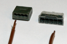
Push-in style connectors will often push a pushing into a flat contact that is also a spring construction, that tends to dig in a little
Tend to not let you pull out solid core without a bunch of force and/or twisting, which is a feature in that it retains the wire.
You can often find these rated for something on the order of 24A.
Lever locks
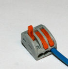
Lever locks clamp a spring down on a wire (varied designs, various of which are smarter than a basic basic pressure plate).
There are a few models and brands, but WAGO's is probably best known (note they make other things as well).
Many are made for wires of sizes like 22AWG to 12AWG, and rated for at least 20A (usually listed on them), e.g:
- WAGO 222 are spring-clamping connectors rated for 400V/32A
- WAGO 221 is a smaller variant of the WAGO 222, rated at a very similar 450V/32A (and 600V/20A)
Wire nuts
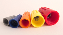
"quick wire connector"
"gel filled crimp connector"

butt connectors
Butt splices, or butt connectors, come in a few variants
- solder seal butt connectors
- A variant of the previous but the central ring is soldering tin instead of glue.
- Needs more heat (a paint stripper is recommended), but is a better connection.
- crimp butt connectors
- Seem to be fairly solid in the hard-to-crimp-down sense
- so probably only usable with the correct crimping tool - I have bad experience without.
- may or may not have a separator in the middle, to ensure equal amounts of both wires are inserted
There seem to be more variants of the idea
On circuit currents
Power - wall plugs
The types are a less formal(verify) way of indicating the common plugs to use around the world.
See:
- http://en.wikipedia.org/wiki/Mains_power_around_the_world
- http://en.wikipedia.org/wiki/Power_plugs
- http://commons.wikimedia.org/wiki/Mains_socket
Some of the more common plugs are listed below
(lettering system as used by some US document on worldwide power)
Some practical knowledge before traveling: https://www.electricalsafetyfirst.org.uk/guidance/advice-for-you/when-travelling/travel-adaptors/
Type F / Schuko / CEE 7/4
(Europe)
-
Type F plug
-
Type F wall socket
Type F plugs/sockets, also known as Schuko (short for Schutzkontakt, roughly meaning 'protective contact', referring to having a contact for protective earth), and standardized in CEE 7/4, are round sockets/plugs with two earth clips on the side, and two guides for a more robust fit in the embedded socket.
It is used in much of (western) Europe, commonly seen in wall sockets and power strips.
Not polarized, though there is an Argentinian variant that apparently is.
The Russian Gost 7396 looks and is similar, but has thinner prongs, so while you can often plug Gost into Schuko sockets, Schuko plugs often don't fit into Gost sockets(verify).
CEE 7/7 plugs
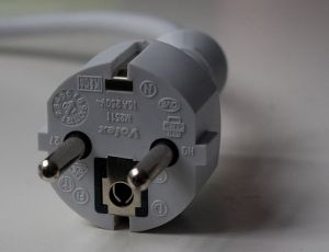
Worth mentioning because it is designed to work in multiple distinct earthed sockets:
- Type F style earth (most of western Europe) and
- Type E style earth (France, Belgium, also Poland, Czech Republic, Slovakia, Denmark).
Seen in wires that must be earthed (so can't be europlugs) and meant for wide sales (that is, catching both type E and type F countries with the same plug).
One good example is computer power supply cables, which are usually CEE 7/7 to C13.
Other, non-earthed European plugs: Type C, Europlug, CEE 7/16, CEE 7/17
Type C exists in round and flat variants.
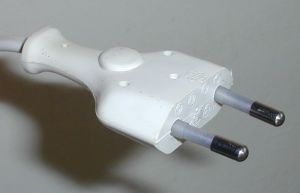
flat type C, also formalized as CEE 7/16, and regularly called 'Europlug' , is an unearthed plug that fits most European-style sockets (Type C, E, F, others).
Some power strips have a few thin-type-C sockets (and Schuko otherwise), because you'll always have a few devices with these and it saves space in that case (and in that case only, as these sockets accept nothing else).
See also:
The CEE 7/17 plug is a something of an unearthed adaptation of 7/16 to mate with Type E, Type F, and round type C sockets.
-
Round type C plug (CEE 7/2)
-
Round type C (CEE 7/1) sockets, on an old power strip
There is also an unearthed round Type C. This is typically considered old, and rarely seen sold anymore, for a few reasons.
socket is CEE 7/1, plug is CEE 7/2.
While the socket (7/1) will accept most any European-style plugs (C, E, F; 7/4, 7/7, others), the round type C plug (7/2) will only really plug into the 7/1 socket, and roughly nothing else, notably not the Schuko socket - it will not plug into Type E or F sockets (blocked by the plastic that guides the earth).
New installations will very typically use only earthed sockets, so the 7/1 socket is harder to find now.
Type E
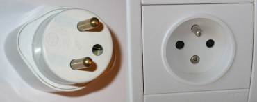
Seen mostly in France, Belgium, Poland, Czech Republic, Slovakia, Denmark(verify)
Looks much like Type C, except for the male ground pin that sticks out.
While it has a fixed orientation, there is no polarization standard. (possibly because that would not apply to other european-style plugs it is fairly compatible with)

Also compatible with others, including (mostly things specifically designed for C, E, and F sockets)
- 7/7 plugs (european earthed round plugs)
- 7/17 plugs (the unearthed but still roundish one)
- and 7/16 plugs (flat unearthed europlug)
Type A, Type B, household NEMA variants, JISC C 8303 Class II
(North America, Japan, some other places)
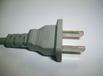
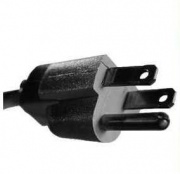
http://en.wikipedia.org/wiki/NEMA_connector
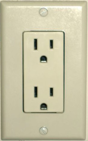
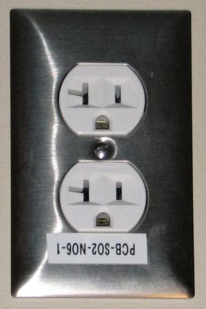
Mainly:
- NEMA 1-15 is the typical 2-prong non-earthed plug, a.k.a. Type A
- NEMA 5-15 is the typical 3-prong earthed plug, a.k.a. Type B
...both rated for 15 amps (with a suggestion of doing no more than ~1300W, because there's a rule that a continuous load should stay under 80% of the rating).
NEMA actually defines a lot more plugs than that
- mostly for
- higher currents - 20, 30, 50, 60A, and/or
- higher voltages, and/or
- doing so on 3-phase (rather less common than split-phase)
- (...all three of which are fairly rare outside of commercial or industrial settings)
- ...most of which you won't see in everyday life
- you may well have seen NEMA 5-20 (horizontal blade on plug, T-shape on socket to accept both 5-15 and 5-20) in commercial settings
- and the four-prong 14-30 (once also the three-prong 10-30 that had no ground), for power-hungry 240V devices at home (like driers)
See also https://en.wikipedia.org/wiki/AC_power_plugs_and_sockets#North_American_and_IEC_60906-2
Polarity
US socket polarization was once central to basic safety, so basically all sockets are polarized.
At the same time, apparently the oldschool 2-pin plug was symmetrical (and the 3-pin wallsocket wasn't required until the seventies)
Many modern devices won't care, and when they use an unearthed (2-pin) 1-15 plug, they can allow it to be plugged in both ways. When they do care about polarization, they do so by having one of the plug's prongs be wider (that's neutral) than the other (that's hot), which will only plug into typical 2-pin or 3-pin sockets one way.
The 3-pin plugs often don't need to bother(verify) with these different sizes, because the presence of the ground pin enforces the polarity.
So yes, you can wire a socket wrong, which is technically unsafe, though practically only for very old devices that connect the chassis to neutral(verify).
Holes?
Various plugs have holes in the prongs. This is not, as some believe, for more friction, or to slot into anything.
It's a manufacturing side effect. In fact, NEMA seems to intentionally spec that if they're there, they should specifically be away from the actual mating part of the surface, so that it doesn't reduce contact area. [31]
Type G, BS 1363 (UK)
Used in the UK and a dozen other countries[32]
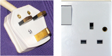
- Oriented
- polarized in the standard (though many everyday devices won't care)
Safety features:
- Earth prong is longer, so a device is earthed before it gets power
- Sockets may have safety shutters (actuated by the longer earth prong)
- Newer variants have the non-ground pins half shielded so it's very hard to reach live copper
Other apparent design considerations:
- All sockets are the same (there is no unearthed socket design)
- Fuses in the plug - often easier to replace than those in the devices
- Wire from bottom means people won't often try to pull it out from the wire, so few break that way (though possibly more break unintentionally)
See also:
BS 1363 replaced the earlier BS 546 in the 1940s, 1950s. BS 546 is still in use elsewhere, see Type D, M
There is also a distinct shaver socket, BS 4573, which looks like a thicker variant of europlug.
Type I

(Australia, New Zealand, China, Argentina)
Type N
South Africa, and a variant seen in Brazil
https://en.wikipedia.org/wiki/AC_power_plugs_and_sockets#Type_N
Type H
Israel
https://commons.wikimedia.org/wiki/File:Israeli-type-H-plugs-and-socket.jpg
https://en.wikipedia.org/wiki/AC_power_plugs_and_sockets#Israel_SI32_(Type_H)
Type J
Switzerland, also seen in Lichtenstein
Europlug will plug into this, earthed variants (or other variants) from elsewhere in europe will not.
Not to be confused with type N
https://en.wikipedia.org/wiki/AC_power_plugs_and_sockets#Swiss_SN_441011_(Type_J)
Type L
Italy mostly sees type L, C, and F
https://en.wikipedia.org/wiki/AC_power_plugs_and_sockets#Italy_(Type_L)
Type K
Denmark
Phase and neutral distance and pins compatible with Schuko/europlug.
Earth is a half-round pin on the plug,
Danish grounded plugs will only fit into a grounded socket.
However, non-Danish european plugs (type E, type F) plugs will mate, but without connecting ground.
https://en.wikipedia.org/wiki/AC_power_plugs_and_sockets#Danish_Section_107-2-D1_earthed_(Type_K)
Less-common Danish variants include
- one pin flat, used in hospitals
- phase and neutral pins slanted, for computer equipment, though reportedly this is more annoying than it is useful.
https://www.plugsocketmuseum.nl/Danish2.html
Type D, M
BS 546 is the older british plug,
and also seen in India, Pakistan, some East African countries, South Africa,
Note that these countries may have other plugs. For example, it seems that:
- India sees C, D, and M
- Pakistan mainly sees C and D
- South Africa sees C, D, M, and N
Three round pins.
There are three different plugs, with larger pins spaced further apart, each with their own current rating.
Because of the three distinct sizes, the three varied plugs will only plug into a socket rated for the same current, although there are sockets that take multiple variants.
The 2 A and 5 A plug are considered Type D, the 15 A plug Type M.
https://en.wikipedia.org/wiki/AC_power_plugs_and_sockets#BS_546_and_related_types_(Type_D_and_M)
https://www.plugsocketmuseum.nl/OldBritish1.html
Type O
When does wall polarity matter?
Power - industrial and multiphase interconnects
https://en.wikipedia.org/wiki/Industrial_and_multiphase_power_plugs_and_sockets
IEC 60309 (Europe)
See also:
Lighting sockets
Edison screw
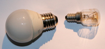
Typical for lightbulb/pear shapes.
The number is the outer diameter of the metal screw part in millimeters.
There's quite a few of them, but by far most common are:
- E26/E27 - common large screw variant
- Apparently there's a correlation where E26 is for 120V countries and E27 for 230V countries(verify),
- they're physically close enough to often fit (verify)
- The more common small variant is usually E14 (Europe) and E17 (US) (verify)
There are a handful of other diameters in use, e.g.
- E11 (Europe), E12 (US) 'candelabra'
- E10 (miniature) in older flashlights, indicator lights, older bike lights
- uncommon now in all those uses, because e.g. LED is more efficient than incandescent
- E39/E40 (giant/'mogul') in industrial / older stage lighting
There are also a whole bunch of adapters,
because within the same country it's the same voltage, and you might want a different style of lamp,
deal with specific or chandeliers, etc.
See also: http://en.wikipedia.org/wiki/Edison_screw#Fittings
bi-post / bi-pin
Many bi-post are IEC 7004 (verify)
You may like overviews from image searches for terms like light bulb socket types diagram
The number specifies the pin distance.
Each distance tends to have a unique socket/plug design, in part to make them more easily identifiable.


Variants with smaller distances are typically small spots (classically halogen), for example:
- GU10 - pins, 10mm distance, widened bayonet-style end (seems to be one of only a few G variants that has that bayonet)
- GX5.3 - pins, 5.33mm distance
- G4 - pins (4mm distance, thinner)
- G9 - flat loops, 9mm between the centers of the loops
These may be easy to find in supermarkets and such - though the exact set varies a little with where you live.
Larger variants like
On relations to the bulbs
A few further details/associations are specified by the letters, e.g. G, GU, GX, GY, GZ.
For example, GZ bulbs use dichroic glass, which means the glass conducts and dissipates heat, so lets out much of the heat at the back.
Power and beam angle may wel be specified [33] though have some inconsistencies in specification.
While endless combinations between socket, bulb, and voltage could exist, there is a lot of consistency in what is actually produced at all - what type of bulb, reflector, and voltage is used on each connector
...so in practice most most further details are (only) implied from most specific references being unique(verify).
For example:
- GU4 are often 12V MR11 bulb
- GU5.3 are often a 12V MR16 bulb
- GU10 are often mains-voltage MR16 (as are various others with >7mm pin spacing)
- GZ10 is like GU10 but does not have a beveled base, which means you can't use GZ10 in GU10 sockets (but can the other way around). The reason seems to be a heat/safety restriction: GU reduces heat to to the rear/socket, GZ does not.
- G6.35 (1mm thick pins)
- GY6.35 (1.25mm thick pins)
- GY6.35, G8, or G9 are more frequently JCD type.
- G9 is often mains, G6.35 is often low-voltage
But don't count on this, because there are exceptions
Shapes and reflectors
- JC, JCD
Refers to a shape - just the small halogen bulbs, no reflector. Can be 12V, 24V, or mains voltage.
Comes in a few base sockets, often one of G6.35, G4, G8(verify)
Apparenly frequently semi-permeable glass, which is why you shouldn't touch it with your oily fingers.
- MR, Multifaceted Reflectors
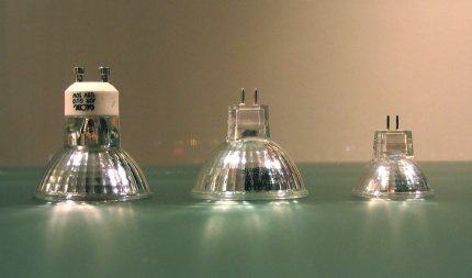
MR (e.g. in MR11, MR16) refers to a Multifaceted Reflector, which produces a more focused beam than simple parabolic reflectors. (see also PAR, which is more specifically an anodized reflector)
MR bulbs are mostly associated with G-style bases, including GU10, GX5.3, and G4.
The number in MRsomething is the bulb diameter - in eighths of an inch, so MR16 bulbs are 5.1cm in diameter, MR11 are 3.5cm.
The combinations of diameter and socket aren't unique - which means it's fairly easy to walk into a store and buy a MR16 and discover you needed one with a GU10 and GU5.3 base and got the other.
You sometimes see specifications of diameter as well as power and beam angle - see [34].
- On voltage
Different MR bulbs may be 12V (most) or higher voltage (some), so never blindly assume.
12V may still be AC, though are often DC in practice.(verify)
LED-based MR-series often won't care since they need to rectify anyway.
Some of the 12V (switch-mode) adapters designed for a string of halogen MRs will not like the low power draw of LED variants. You need a transformer that is not trying to be clever, one designed for lower draw, attach more lights on a single adapter, or get one designed with LEDs in mind.
Other notes
See also DIY_optics_notes#Stage_lighting.
Specialist
XLR
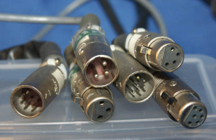
This is about XLR as the whole connector family.
If you care about XLR3 as used around microphones, see Microphone_cabling
If you care about XLR3 or XLR5 being used for DMX, see DMX.
Diameter:
Exists in a number of variations
- XLR3, seen as:
- a balanced audio connector, primarily for microphones (in the past also some equipment interconnections and speakers, including powered ones - now less so, probably due that last bit leading to some pricy mistakes)
- DMX in a lot of practice
- AES/EBU digital audio (mostly in some older digital gear)
- XLR4 - used e.g. intercoms, and apparently once relatively universal for power for in TV and film industries ,
- XLR5 - in the DMX specs (but many simpler DMX devices use only XLR3 because two pins were never used)
- XLR6
...and various others, some of which are considered obsolete.
The two most recognisable uses are probably in the event industry:
- balanced audio (XLR3)
- DMX (in practice mostly XLR3, in theory XLR5)
(also note that audio cables and DMX cables, while they look similar, are not interchangeable for other reasons. It'll work fine on a test-bench scale, but will have issues on large scale)
There are also some lesser-seen and specific variants, such as
- PDN to go between amps and speaker
- LNE, that carries just mains power, but was apparently never really used
See also:
See also The_XLR_pin_1_problem
Kleintuchel

DIN 41524, a.k.a. kleintuchel (klein means small and Tuchel' is a company name -- so this is much like saying 'DIN plug' or 'RCA connector' - understood well enough, but only due to context), or something slightly more descriptive like "DIN with a screw ring".
Seen around some older microphones.
Three pins, for differential output and a shield, so basically the same idea as XLR.
Apparently easily adapted to XLR, though note that some companies were inconsistent with polarity on kleintuchel plugs, so when you use more than one mic in a setup, you may want to make these adapters microphone-specific if you care about phase mistakes.
In that (slightly distorting macro) image, the top is the cable, bottom is the microphone. That center hole is not functional or typical(verify).
Grosstuchel
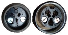
DIN 41624, a.k.a grosstuchel
Seen around some older microphones.
Small mic plugs
There are a few different small, XLR-looking plugs and sockets,
mostly seen on worn wireless microphones, some field recording kits, and otherwise fairly rare.
These seem to be used for being a locking plug that is fairly solid.
It seems that plugs can vary per manufacturer,
pinouts can vary even if the same connectors are used (varying a little by brand and context),
and some aren't even differential (not as necessary for short cables).
This seems to frequently be the plug called Switchcraft TA3 (The female TA3F on the microphone end).
"Mini XLR" doesn't really exist(verify), and seems to often refer to Switchcraft TA3, sometimes others like it(verify)
There is also a variant that uses TA4 connector (4-pin, TA4F on the microphone end), also with slightly varying pinouts.
I've seen TQG and Tiny-QG refer to both TA3 or TA4. Presumably this is Switchcraft trying to apply a brand/trademark?(verify).
Audio Technica seems to use a Hirose 4-Pin connector
I've also seen mention of LEMO plugs, and even just reuse of TRS.
The wiring link below seems a decent list.
See also:
XLR+TRS combo

A single socket that accepts both XLR, and 1/4" (6.35mm) TS/TRS jacks.
I'm unsure whether Neutrik developed these, but there seems to be no singular name or singular producer(verify) (anymore),
yet 'Neutrik Combo' seems to be one of the better-understood references.
Mainly used to save some space on audio devices that want to accept both of these pro-audio inputs in less (rack) space.
https://www.neutrik.com/en/neutrik/products/plugs-jacks/jacks/combo-i-series
Speakon
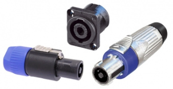
Neutrik Speakon is used in some professional audio, as a amp-to-speaker connection of an already amplified speaker signal.
It seems to have been introduced to be a unique, non-confusable plug, because it was (and still is) not uncommon to use TS plug that could carry either a voltage signal or already-amplified audio, which has the issue that plugging a powered output into a signal input would probably damage that input. (TS inputs are often protected against this, e.g. with a varistor, so that you don't blow up things so much)
See also: http://en.wikipedia.org/wiki/Speakon_connector
powerCON
Neutrik's powerCON is a few related connectors that connect 3-pole mains power (20A or 32A).
Rated for a little more current than typical wallplug interconnects, and smaller than most of them.
There is no standardized voltage(verify). Connectors are rated for 250V, but in 120V countries they'll typically connect that(verify).
There are variants that are rated IP65 while connected, which makes them useful for outdoor events.
powerCON blue / grey [35]
- Type 1
- source side
- blue
- locking (bayonet-style)
- 20A
- not disconnectable under load
- Type 2
- drain side
- grey
- locking
- 20A
- not disconnectable under load
Type 1 and 2 are intentionally different, so that it should be impossible to plug a short.
- Powercon 32A [36]
- 32A
- source side only?
- 16A
- disconnectable under load
- type 1/2 variants redesigned to be disconnectable under load (verify)
- 2020?
https://en.wikipedia.org/wiki/PowerCon
Fiber
Low power or signals
Sure, there are many things you can abuse the other way, but there are also things that are more designed (or more accidentally quite fit) to carry both low current power, or signals.
Testing things
Banana plugs
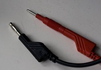
The thinner (2mm) not-so-banana plug on the right (adapter) that many would consider a multimeter probe
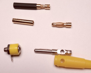
The banana plug is named for the curvy lengthwise springs that friction-lock the plug.
Shapes vary, and not all such 4mm plugs have a friction-lock design, or the same one if they do.
Length was typically 20mm, though e.g. the US seems to use 15mm, and there's more variation.
They might be rated for something like 30V, 15A -- BUT products vary and some are much flimsier and will not be rated like that.
(It seems the main reason for the low voltage is not isolation in the arcing sense, but safety in the sense that the contact is entirely exposed. Variants with fixed shrouds, or sleeves that retract, may be rated for higher voltages.)
The 4mm version often carries lowish-current power or occasionally audio - it is seen on things like
- measuring devices, such as multimeters, bench power supplies, and such
- these are often also stackable somehow (4mm hole in the back, or side)
- and e.g. banana-to-BNC for oscillosocopes (handy for non-HF frequency measurements)
- amp/speaker connections
- easy to replug
- capable of dealing with moderate current
There is a 2mm plug seen in similar situations - seemingly mostly multimeters, probably because it's a nice tradeoff in study enough to not break, and thin enough to poke at many smaller components.
It's not really referred to as a (variation of) banana plug, because the lengthwise springs are not there, but I haven't found a better place to group it under.
See also:
Crocodile clips / Alligator clips
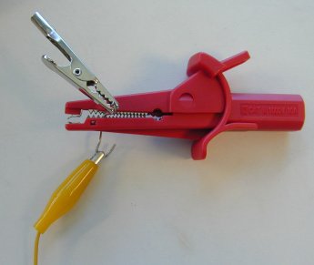
Crocodile clips are useful for making a temporary electrical connection that will be decent and stay on.
The ones in the image here are a few cm large and don't carry much current.
Two of these plug onto banana plugs, for ease of use with multimeters.
There are large ones, seen e.g. around car batteries, that are much beefier.
See also:
IC clips
Test hooks / pincer clips / IC grabbers
...and probably other names.
Details vary, but generally these are small grabby springy things that extend and separate when pushed by hand, and pull in and close when you let go.
This gives comfortable temporary connections on pins down to 2mm pitch or so, where alligator clips would already be troublesome due to their thickness.
The image shows a very cheap variant (one extended), but even they still work pretty well.
Pogo pins
Spring loaded conductive connectors.
Mostly used in automated testbeds, where a PCB often needs to be pressed into a handful of these,
and in some other places where you want many points of non-permanent contact.
See also:
Smaller JST connectors
JST refers to a company that makes many series of plugs.
The below are mostly used as PCB (inter)connectors useful for data signalling, though many are rated for (on the order of) 1, 2, or 3A, so also useful to transfer some power.
A few of the series:
JST RCY

socket and plug
Pitch: 2.5mm pitch
Pins: 2 (not a series)
keying/mating: round shape that guides into shell
Seen in RC vehicle applications, there known as JST connector, BEC connector(verify), P connector(verify)
Rated for 3A (with AWG22(verify)).
See also:
JST XH series

Pitch: 2.5mm
Pins: 2 to 20
Keying/mating: two slits near the side of one long end, with some slight bayonetting (works out more as a friction thing)
Rated for: 3A (with AWG22)
Perhaps most recognized as a connector commonly on lithium batteries (2 or more pins depending on how many cells, for balance charging)
See also:
JST EH series

Pitch: 2.5mm pitch
Pins: 2 to 15
Keying/mating: socket one side unshrouded, plug one side wider; slits on short edges
Rated for: 3A (with AWG22)
See also:
JST SM series
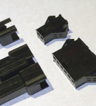
2.5mm pitch
Pins: 2 to 18
Keying/mating: locking clip in the middle (on 2-pin it's the entire width) and keying on middle of one long side, 'wings' on the short sides
Rated for: 3A
"SM2 connectors" seem to refer to the 2-pin variant(verify)
See also:
JST PH series


Pitch: 2.0mm pitch
Pins: 2 to 16
Keying/mating: plug has two slits on the one side long, socket is open between them (one slit and nothing open on the 2-pin variant)
Rated for: 2A (with AWG24)
See also:
JST ZH series

Pitch: 1.5mm
Pins: 2 to 13
Keying/mating: two slits on the sides (the shortest ends)
Rated for: 1A (with AWG26)
See also:
JST SH series

Pitch: 1.0mm
Pins: 2 to 20
Keying/mating: slits on short end(verify)
Rated for: 1A (with AWG28)
See also:
JST VH series
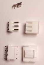
Pitch: 3.96mm
keying/mating: slots to the side, clip
Rated for 10A (with AWG16)
See also:
Smaller molex connectors
Molex KK
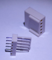
Pitch: 2.54mm (the most common that I've seen)
Pins: 2 .. 36
Pitch: 3.96mm
Pins: 2 .. 24
Pitch: 5.08mm
Pins: 2 .. 12
Keying/mating: slits around socket's wall, ridge along wall for friction
See also:
Micro and pico variants
https://www.molex.com/molex/products/group/micro_connectors
- picoblade
- 1.25mm pitch
- molex picoblade
Smaller AMP connectors
(The company is now TE Connectivity, previously Tyco Electronics, and AMP far before that, but we tend to still call them connectors AMP)
MTA
- single row, 0.1" / 2.54mm pitch
- single row, 0.156" / 3.96mm pitch
Circular metric
Circular metric and circular industrial don't refer to any one connector or standard, but informally to connectors that are round.
Metric seems to refer to a metric screw barrel, industrial to 'it looks sturdy' and probably to a few specific series of plugs that I'm not aware of yet.
It's a basic idea implemented in different ways by various companies,
which is why they exist in snap-in, bayonet, push-pull variants; metal and plastic barrels; various types of internal keying, and more variations.
In my (very biased) recollection I've seen the metal variants more around larger and industrial machines,
probably because they're a way to have a sturdy, many-pin, and somewhat isolated control signal interconnection.
Device producers may favour one of them internally, so you probably see some of these more consistently than others.
And some are largely convention. Say, some specific LEMO plugs (among many - like DIN and Molex and other cases, we're naming an entire company[39]) are seen around cameras -- but with varying pinouts (and of varied types, there's also e.g. LEMO optical and triax both used around video).
Some are even standard.
Say, there's the GX series connectors seen fairly consistently around aviation, usually smaller and fewer pin (I see mention of GX16, GX20, GX12, the number is the barrel diameter in mm)
Down to some cheap plastic (but waterproof) connectors seen around garden/christmas lighting, distinctly keyed (which in a few examples I found correlated with the voltages used).
...and seemingly everything inbetween.
Mounts, chip carriers, packages, board connectors
Mounts, chip carriers
Packages refer to the specific design and size of something a particular component is housed in.
You will often see specific component types (and particularly specific models) in certain specific packages/mounts. For example, transistors are often seen in SOT or TO, diodes often in DO, LEDs often in what seems to be called T1, and so on.
Surface mount which may seem recent but has been around since the sixties. Surface mount has introduced a lot of specific smaller packages.
It's hard to summarize them and give a decent impression of which are more common.
On pitch
Pitch refers to the spacing of pins (more often mentioned in through-hole components, as those are fairly wide-purpose, while suface mount components tend to be more specialized packages)
Common pitches include
- 2.54mm (0.100")
- 2mm (0.079")
- 1.27mm (0.050")
- 0.8mm (0.031")
- 0.5mm (0.019")
There are a number of different measures that can be relevant in addition to pitch.
See for example http://en.wikipedia.org/wiki/List_of_electronics_package_dimensions#Through_hole_pin_dimension_reference
SMD/SMT versus though-hole
There is a noticable distinction in through-hole versus surface mount:
SMD (Surface Mount Devices) and SMT (Surface Mount Technology) often means leads that end flat on the circuit board, to be soldered in place (often with reflow soldering, wave soldering, or such).
SMD seems to have become popular since approximately the eighties. There are SMT variants of ICs, resistors, capacitors, and various other sorts of packages.
SMD/SMT can also be seen as the top of a hierarchy of a load of specific packages.
The style it is replacing has been (retroactively) named though-hole, occasionally abbreviated to THT (though-hole technology).
See also:
- http://en.wikipedia.org/wiki/Surface-mount_technology
- http://en.wikipedia.org/wiki/Through-hole_technology
- http://en.wikipedia.org/wiki/Chip_carrier
Packages, roughly from fewer to more leads
TO, SOT, SC, some small SMD
TO, SOT, SC, SOD refer to a style of making packages, all with quite a few variants, and usually with a small pin-count (often between 2 and perhaps 7, usually between 3 and 6).
While they have names referring to specific uses and sizes (TO: 'transistor outline', SOT: 'small-outline transistor', SOD: 'small outlide diode'), most of these packages end up seeing many other uses - particularly those packages that handle more than average power (heat).
Note that a number of specific packages have names in more than one of these series.
Many of these are THT, some SMT, some usable as both as they have long pins (some bending involved for THT).
TO ('transistor outline')
TO is often used when there is more-than-negligible current involved (mostly because of the package's thermal capacity), e.g. for transistors, regulators, darlingtons, power resistors.
-
TO-92
-
TO-220
-
TO-226

Specific TO packages include:
- TO-220 (images) (good heat dissipation, frequently used where power is involved)
- TO-236-AA (resembles SOT-23, but sizes are a little different)
- TO-252(-AA), a.k.a. DPAK (4.6mm pitch)
- TO-263(-AB), a.k.a. D2PAK (effectively 5.08mm pitch, because the middle isn't a pin(verify))
- TO-262 a.k.a. I2PAK
- TO-251 a.k.a. IPAK
SOT ('Small Outline Transistor')
A surface-mount package, used for transistors, but also rectifiers, regulators, and more.
There are quite a few variations, many with pins that are wider for better heat transfer.
- SOT-23 - with different amounts of acually present pins, sometimes referred to as:
- SOT-23-3
- SOT-23-5
- SOT-23-6
- SOT-23-8
- SOT-89
- SOT-223 (three-terminal)
- SOT-232 (three-terminal)
- SOT-363
- SOT-353
- SOT-416 (SC-75) (three-terminal)
- SOT-723 (three-terminal)
- SOT-883 (three-terminal)
SC looks like SOT, but has thinner leads (verify)
- SC59
- SC59-5
- SC59-6
- SC-74A
- SC-70
DO
THT-style diodes are often seen in DO-xx, for example
- DO-35
- DO-15
- DO-41
LEDs often in [40]
- the circular plastic housing is often mentioned just by its radius, though seems to also be called:(verify)
- T-1 (3mm)
- T-1 3/4 (5mm)
- T-3/4 (2mm)
seems to be called T1(verify) (but more commonly mentioned just by its radius)
- flat housings (THT connectors)
- SMT
SIP
-
SIP
-
You can use pin headers as SIP package
Pitch: 2.54mm
Single Inline Package. Regularly 0.1" pitch. Hardly a package at all.
DIP
Pitch: 2.54mm (most variants)
-
16-pin DIP socket; 14-, 6-, and 4-pin DIP ICs
(all 0.3" row spacing) -
DIP-24 with 0.3" row spacing
DIP-24 with with 0.6" row spacing
DIP (also DIL): dual in-line package, usually for ICs which need relatively few pins (up to 64 or so, usually fewer).
DIP often implies 0.1 inch (2.54 mm) pitch.
Most DIP chips have a row spacing of either 0.3 inch (7.62 mm) or 0.6 inch (15.24 mm). DIP is now often assumed to be 0.3" (which is also sometimes called skinny DIP(verify)).
Since DIP is largely about pin spacing, many things besides ICs can use or be compatible with DIP, or make DIP sockets useful for other things than DIP ICs.
For example:
SO
SOIC (Small-Outline Integrated Circuit)

Pitch: 1.27mm
Pin count variation:
- SOIC-8
- SOIC-14
- SOIC-16
There are wider variants.
See also:
SOJ
Pitch: 1.27mm (verify)
SOIC with J-type leads (instead of gull-wing leads).
SOP
Pitch: 1.27mm, and also 0.80mm, 0.65mm, 0.5mm, 0.4mm
Followed SOIC(verify)
- TSOP (Thin Small Outline Package) [41]
- pitch: 0.5, 0.55, 0.65, 0.8, 1.27mm
- SSOP (Shrink Small Outline package) [42]
- pitch: 1.27mm (verify)
- TSSOP (Thin Shrink Small Outline Package) [43]
- Pitch: 0.65mm
- VSOP (Very Small Outline Package) [44]
- 0.65 mm
- MSOP (mini SOP)
- Pitch: 0.65mm
- QSOP (Quarter size SOP) [45]
- Pitch: 0.625mm (25 mils), usually
- µSOP (micro SOP)
- Pitch: 0.5mm
- HSOP - SOP with heat wings
- HSSOP - SSOP with heat wings
- CSOP
PLCC (Plastic Leaded Chip Carrier)
PLCC chips have J-shaped leads that wrap around the side and under the IC.
- the side allows it to be seated in a PLCC socket (can be handy for replacement ability, or when heat is critical),
- the fact that they wrap lets them also be soldered to surface-mount pads.
Pitch: 1.27mm
PLCC sockets have slots across one diagonal, for a specific PLCC extractor tool that eases removal.
Was also used in early CPUs, after DIP and before more specialized sockets.
Actually sits in a group called JLCC (J-Leaded Chip Carrier), subdivided into:
- PLCC (Plastic ~), which seems much more common of the two
- CLCC (Ceramic ~), which seems used mostly for in some high-temperature and prototypes(verify)
See also:
Flat no-leads package, Micro Leadframe
Chip Scale Package
QFP

Quad Flat Package is a number of related packages that use gull wing leads (out, down, and out again parallel with the SMD pad it's intended for)
There are a dozen named specifics, which mostly just vary in things like
- smaller-pitch variants
- heat sinking
- material (plastic, ceramic)
- thickness (some are low profile)
Pitch: 0.80mm, 0.65mm, 0.5mm, 0.4mm, 0.3mm (more?)
https://en.wikipedia.org/wiki/Quad_flat_package
PGA
Pitch: 2.5mm, 1.27mm
Plastic or ceramic (PPGA, CPGA)
BGA
Pitch: 1.5mm, 1.27mm, 1.00mm, 0.8mm, 0.5mm
See also
Unsorted chip mounts
PCB connectors
('PCB connectors' is probably not the best name, I'll think of another)
Headers

Known variably as pin headers, just headers, as breakaway headers, as and under various other names.
Often 2.54mm (0.1") pitch.
Also the things that jumpers (sometimes known as shunts) sit on.
And you could call a row of headers a Single In-Line package (SIP) without too much of a stretch.
PCB headers are a fuzzy, wider concept, and can refer to pin headers as well as many more specific deivations, then often seen in shrouded and/or keyed (notched) form.
One simpler example is KK-family molex, which mostly add bits of plastic as polarity protection but will fit on basic headers as long as they have the same pitch.
PCB mount screw terminals

Screw terminals in general may be little more than screw to fasten down a wire to a metal plate.
The variant for PCBs, with pins underneath you can solder, is usually also shrouded.
Available in varied pitches, though mostly larger, like 2.54mm, 3.5mm, 3.96mm, 5.08mm, (verify)
Combining these with bootlace ferrules tends to look like fairly neat work.
See also:
- http://images.google.com/images?q=pcb%20screw%20terminals
- http://en.wikipedia.org/wiki/Screw_terminal
- http://www.google.com/images?q=luster%20terminal%20OR%20lustre%20terminal
Ferrules

Ferrules (bootlace ferrules, apparently referring to aglets?), also known under a few other names are sleeves meant to crimp onto stranded wire.
They are comparable to some variants of crimp pin:
They wrap a shell around all strands (so avoid some issues with a single strand making contact you don't want).
They make particular sense around stranded wire, in that
- there is less risk of one of the barely-visible strand going off to the side and touching something it shouldn't.
- screw terminals won't damage the strands (so the wires are a little more reusable)
The wider plastic part means they're not great when there are many wires to be connected cramped side by side, but this is not often a real issue - they're still fine in most sizes of screw terminals.
Compare also to butt splices
Euroblock
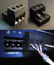
Euroblock, also known as Phoenix connector, has screw terminals on one side and a snap-in connector on the other.
Can be convenient and fast working on semi-permanent setups, where you frequently want to re-plug things in the same way, and/or plug around comparable items.
It seems mainly used around
few-wire control signals (e.g. RS-485),
and audio setups (often for balanced audio(verify)).
https://en.wikipedia.org/wiki/Euroblock
DIN 41651
DIN 41651 (image search) includes various series of fairly common insulation-displacement connectors, including IDC.
Usually two-by-many pins, also seen in four-by-many.
Often 2.54mm (0.1") pitch, smaller variants exist.
Variations:
- With or without alignment notch (verify)
- With or without strain relief
- With or without latches
DIN 41612 / IEC 60603-2
"DIN 41612" OR "IEC+60603-2" (image search) resembles DIN 41651 (IDC and such), but applications are more specialized, and often has more connections (dozens is not unusual, up to over a hundred).
Commonly two-by-many or three-by-many pins.
Used by some pluggable rack systems, e.g. VMEbus, which is why a lot of image hits will be the 3x32 variant.
Flexible flat cable (FFC)
Could refer to any cable that is flat and flexible (and is thinner than ribbon cable), but FFC usually refers to a fairly specific type commonly seen used as pluggable interconnects in tight spaces such as inside laptops and phones.
Seen in various colors - white, transparent brown/orange, gray, black, and others (color can correlate somewhat with size/pitch).
Common pitches include 0.5mm, 1 mm, 1.25mm, 2 mm.
FFC connectors often refer to the PCB sockets that accept the end of these cables (though a few designs opt for specific connectors that take less space).
See also:
Related are Flexible Printed Circuits (FPC), which are circuits built fairly directly onto these cables (often using small SMD components, and often fairly simple circuits) - image search
(Card) Edge Connectors
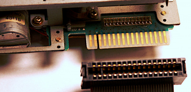
Refers to connections where one side is part of the PCB itself, with traces going to the edge in regular spacing, meant to plug into a spring connector socket,
That socket is often either fixed on a PCB (consider RAM, PCIx and similar), or sometimes in the middle of a cable (consider 5.25" floppy drive connectors)
Consider e.g.
- 5.25" floppy drives (two-sided, 34-pin)
- DRAM modules (rather smaller pitch than the above)
- various game cartridges, including NES, SNES, Sega, N64, Gameboy, DS, Switch, and more[46]
- ...with some gray area -- many memory cards do not technically qualify - they look the same as these cartridges, except that the contacts are often not traces on a PCB (presumably often for the good reason of putting less tension on the actual PCB?(verify))
May be one-sidede or two-sided.
See also:
Board-to-Board connectors
Broadly refers to anything that does many-channel signaling between distinct circuit boards.
Can refer to
- setups that directly fit boards together (often fairly specialized, small, pin-dense connectors)
- things only useful for board connectors, like FFC
- wire-to-board used to connect boards, like IDC
- Specific physical layouts, as simple as Arduino shields' specific layout of pin headers
...and more
Elastomeric connectors
Elastomeric connectors, a.k.a. ZEBRA strips,
https://en.wikipedia.org/wiki/Elastomeric_connector
